Percutaneous vertebral pedicle puncture guider

A pedicle and guide technology, applied in the direction of puncture needles, fixators, internal fixators, etc., can solve the problems of penetrating into the spinal canal to damage nerves, cumbersome operations, and penetrating out of the vertebral body to damage large blood vessels, so as to reduce punctures The number of times, the effect of improving accuracy and reducing damage

Inactive Publication Date: 2017-06-20
THE FIRST PEOPLES HOSPITAL OF NANTONG
View PDF0 Cites 2 Cited by
  • Summary
  • Abstract
  • Description
  • Claims
  • Application Information

AI Technical Summary

Problems solved by technology

[0002] With the development of minimally invasive technology, percutaneous spinal pedicle puncture to establish a working channel, inject bone cement or implant pedicle screws has been widely used in the reconstruction of spinal stability. Various navigation devices in orthopedics can accurately guide the puncture, but their The high price limits its popularization. The traditional percutaneous puncture method is completed by doctors based on intraoperative X-ray perspective and clinical experience. In actual operation, the axis of the pedicle follows the position of the operation and the anatomical segment. The direction of the puncture varies greatly, and the puncture direction needs to be adjusted repeatedly during the operation. The puncture needle cannot be effectively fixed to the patient's back when it does not enter the vertebral cortex, and a small movement may cause large changes when adjusting the direction of the needle. Deviation, blind puncture operation may cause complications such as penetrating into the spinal canal and injuring nerves or penetrating out of the vertebral body to injure large blood vessels. Therefore, we propose a percutaneous spinal pedicle puncture guide

Method used


Image

  • Percutaneous vertebral pedicle puncture guider
  • Percutaneous vertebral pedicle puncture guider
  • Percutaneous vertebral pedicle puncture guider

Examples


Embodiment Construction

[0019] The following will clearly and completely describe the technical solutions in the embodiments of the present invention with reference to the accompanying drawings in the embodiments of the present invention. Obviously, the described embodiments are only some, not all, embodiments of the present invention.

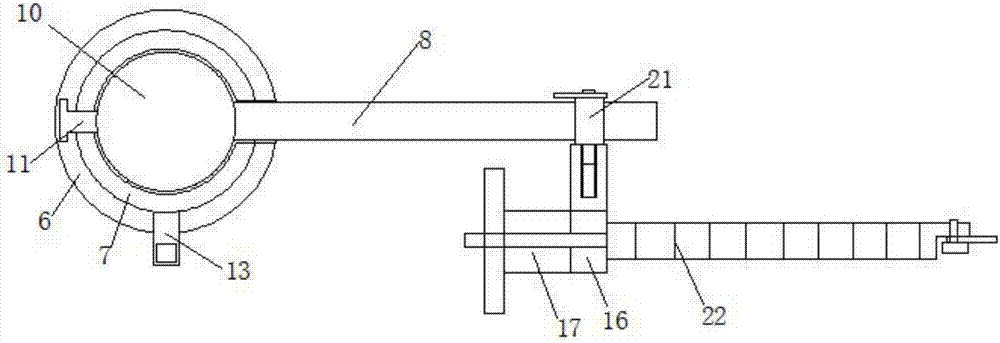
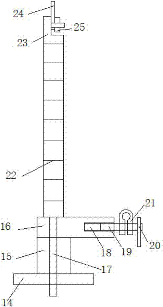
[0020] refer to Figure 1-5 , a percutaneous spinal pedicle puncture guide, comprising a first clamping block 1 and a rotating disc 14, the top end of the first clamping block 1 is welded with a first threaded rod 4, and the first threaded rod 4 is provided with a second clamping block 2 and the first fixed block 3, the second clamped block 2 is located between the first fixed block 3 and the first clamped block 1, the second clamped block 2 is slidably connected with the threaded rod 4, the first fixed block 3 and the first fixed block 3 threaded connection, the top of the threaded rod 4 is welded with a support rod 5, the top of the support rod 5 is welded with a c...


PUM


Abstract

The invention discloses a percutaneous vertebral pedicle puncture guider which comprises a first clamping block and a rotating disc. A first threaded rod is welded to the top end of the first clamping block and provided with a second clamping block an a first fixed block, the second clamping bock is located between the first fixed block and the first clamping block, the second clamping block is connected with the threaded rod in a sliding mode, the first fixed block is in thread connection with the first fixed block, a support rod is welded to the top end of the threaded rod, a connecting block is welded to the top end of the support rod, a first groove is formed in the top end of the connecting block, and a rotating block is connected into the first groove in a sliding mode. According to the percutaneous vertebral pedicle puncture guider, the angle of a puncture needle is adjusted and fixed through a ball, a rotating rod and a universal tube, the phenomenon that in an operation, the puncture direction needs to be adjusted repeatedly is reduced, a deviation appearing due to small movement in the needle insertion process is reduced, the phenomenon that complications of causing the nerve injury by inserting the needle into a vertebral canal, causing the large blood vessel injury by going through vertebral body and the like are likely to occur in the blind puncture operation is reduced, and the accuracy and safety of percutaneous vertebral pedicle puncture are improved.

Description

technical field [0001] The invention relates to a special medical device for percutaneous spinal pedicle puncture, in particular to a percutaneous spinal pedicle puncture guide. Background technique [0002] With the development of minimally invasive technology, percutaneous spinal pedicle puncture to establish a working channel, inject bone cement or implant pedicle screws has been widely used in the reconstruction of spinal stability. Various navigation devices in orthopedics can accurately guide the puncture, but their The high price limits its popularization. The traditional percutaneous puncture method is completed by doctors based on intraoperative X-ray perspective and clinical experience. In actual operation, the axis of the pedicle follows the position of the operation and the anatomical segment. The direction of the puncture varies greatly, and the puncture direction needs to be adjusted repeatedly during the operation. The puncture needle cannot be effectively fix...

Claims


Application Information

Patent Timeline
Patent Type & Authority Applications(China)
IPC IPC(8): A61B17/34A61B17/70A61B17/90
CPCA61B17/3403A61B17/3472A61B17/7074A61B17/88A61B2017/3405A61B2017/564A61B17/90
Inventor 陈佳佳崔志明保国锋徐冠华孙郁雨张金龙
Owner THE FIRST PEOPLES HOSPITAL OF NANTONG
Why Eureka
Try Eureka