Semi-trailer girder and semi-trailer
A semi-trailer and girder technology, applied to vehicle parts, substructure, transportation and packaging, etc., can solve problems such as easy breakage, and achieve the effect of life extension
- Summary
- Abstract
- Description
- Claims
- Application Information
AI Technical Summary
Problems solved by technology
Method used
Image

Examples
Embodiment 1
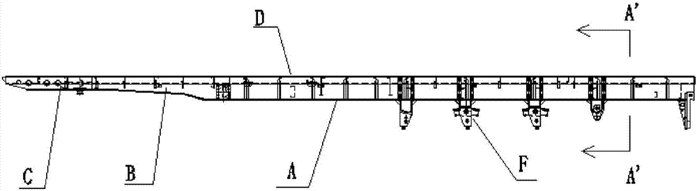
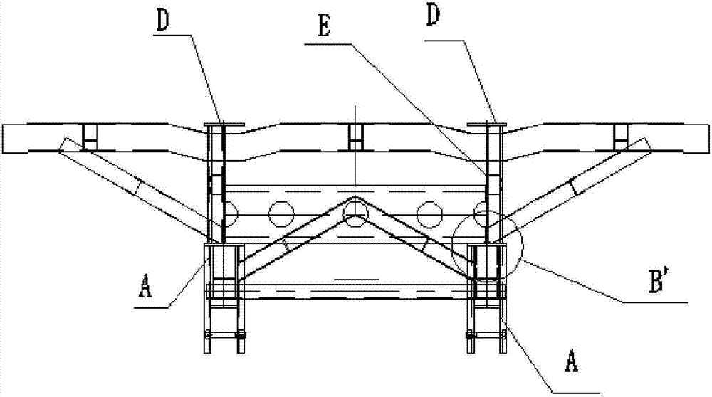
[0047] see Figure 4 , Figure 5 and Figure 6 , the first embodiment provides a semi-trailer beam structure, including the rear lower wing 10 and the suspension 40;
[0048] Wherein, the rear lower wing 10 includes a lower wing flat plate portion 11 and two lower wing side plate portions 12, and the two lower wing side plate portions 12 are located on opposite sides of the lower wing flat plate portion 11. side, forming a structure with a U-shaped cross section;
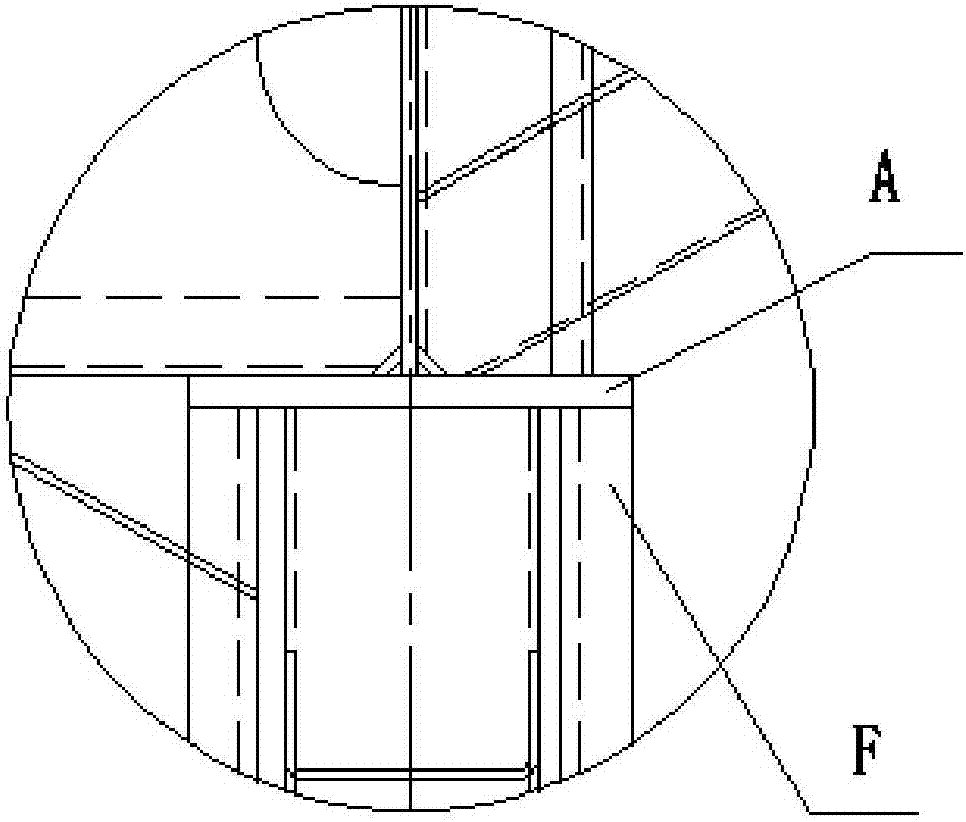
[0049] The opening of the U-shaped rear lower wing 10 is set upwards or downwards, and the flat plate portion 11 of the lower wing is connected to the suspension member 40 .
[0050] Analyzing the structure of the above-mentioned semi-trailer frame, it can be seen that it is mainly composed of the rear lower wing plate 10 and the suspension part 40 . Wherein, the rear lower wing plate 10 also includes a lower wing plate portion 11 and two lower wing plate side plate portions 12, and the two lower wing plate side...
Embodiment 2
[0053] see Figure 7 , Figure 8 and Figure 9 , the present embodiment 2 provides a semi-trailer frame, which also adopts the above-mentioned technical structural relationship; for example: the present embodiment 2 provides a semi-trailer frame, including the rear lower wing plate 10 and the suspension part 40; wherein, the The rear lower wing plate 10 includes a lower wing plate portion 11 and two lower wing plate side plate portions 12, and the two lower wing plate side plate portions 12 are located on opposite sides of the lower wing plate plate portion 11, forming The cross section is a U-shaped structure; the opening of the U-shaped rear lower wing 10 is set upwards or downwards, and the flat plate portion 11 of the lower wing is connected to the suspension 40 .
[0054] The main structure of the semi-trailer frame provided in the second embodiment is the same as that of the semi-trailer frame in the first embodiment; however, the semi-trailer frame provided in the sec...
Embodiment 3
[0068] Correspondingly, the third embodiment provides a semi-trailer, which includes the semi-trailer girder involved in the second embodiment above (the specific structure of the semi-trailer girder will not be repeated one by one), and it also includes a tractor; The girder is connected to the tractor.
[0069] Apparently, the semi-trailer provided by the present invention has all the advantages of the semi-trailer frame in the second embodiment above, so no more details are given here. The rear lower wing plate 10 of the semi-trailer frame in the semi-trailer is not easy to break at the joint with the suspension member 40, and the service life has been prolonged (see also the above-mentioned embodiment two). Figure 10 ).
PUM
 Abstract
Description
Claims
Application Information