Chambering method of chambering equipment on construction site

A technology for construction sites and equipment, used in drilling equipment, earth-moving drilling, drilling without stripping topsoil, etc. The effect of high longitudinal depth and stability

Inactive Publication Date: 2017-06-20
CHINA MCC5 GROUP CORP
View PDF6 Cites 13 Cited by
  • Summary
  • Abstract
  • Description
  • Claims
  • Application Information

AI Technical Summary

Problems solved by technology

[0004] The technical problem to be solved by the present invention is that when the existing hole reaming method reams the bottom of the pile hole, the longitudinal depth of the hole expanded is low, and the force after grouting cannot meet the requirements, and the efficiency is low, which easily leads to equipment damage, which is not necessary. Satisfied with the use, its purpose is to provide a method for reaming holes on the construction site. The holes reamed by this reaming method have a variable diameter and a high longitudinal depth. After grouting, the bearing force is increased, and the stability of the building above can be maintained. It has high hole expansion efficiency and can protect the safety of equipment

Method used


Image

  • Chambering method of chambering equipment on construction site
  • Chambering method of chambering equipment on construction site
  • Chambering method of chambering equipment on construction site

Examples


Embodiment 1

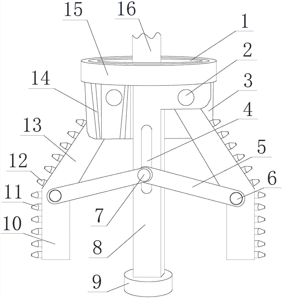
[0026]Such as Figure 1 to Figure 3 As shown, a hole reaming method for hole reaming equipment on a construction site includes a connection seat 15, a connection hole 1 is arranged in the connection seat 15, and the connection hole 1 is a threaded hole, which is used to connect the connection seat 15 to other equipment , the connection hole 1 is not a through hole, so that the top of the support column 8 can be fixed to the connection seat 15, and two mounting plates 3 arranged parallel to each other are arranged below the connection seat 15, and the top ends of the mounting plates 3 are connected to the connection seat 15. The bottom end of the bottom is fixed vertically, and the support column 8 passes through the area between the mounting plates 3 and is fixed with two mounting plates 3 as an integral structure at the same time. The scraping mechanism includes an inclined plate 13 and a vertical plate 10 connected as an integral structure. The plate 10 is parallel to the su...

Embodiment 2

[0029] Such as Figure 1 to Figure 3 As shown, on the basis of the above embodiment, the top of the support column 8 is concaved to form a cavity, the bottom surface of the connecting hole 1 is concaved to form a through hole, and the through hole communicates with the cavity, and a connecting rod 16 is arranged in the cavity. And the top end of the connecting rod 16 passes through the through hole and the connecting hole 1 of the connecting seat 15 , and the connecting rod 16 can move along the axial direction of the support column 8 in the cavity and the connecting hole 1 . In order to keep moving smoothly, it is better to design the axis of the support column, the axis of the connecting rod 16, the axis of the connecting hole 1, the axis of the through hole and the axis of the cavity to coincide.

[0030] Two through grooves 4 are arranged on the side wall of the support column 8, and the through groove 4 is arranged symmetrically on the side wall of the support column 8 an...

Embodiment 3

[0032] Such as Figure 1 to Figure 3 As shown, on the basis of the above embodiment, a connecting arm 5 is arranged between the scraping mechanism and the support column 8, the number of the scraping mechanism is two groups, and the connecting arms 5 connected to each group of scraping mechanism are two pieces, and the scraping mechanism And the support column 8 is arranged between the two connecting arms 5 connected with it, the connecting arm 5 is provided with a pin 6, and the pin 6 on the same group of scraping mechanisms passes through the two connecting arms 5 and the inclined plate 13 at the same time and the connection between the vertical plate 10, and the connecting arm 5 can rotate around the pin one 6, the other end of the connecting arm 5 is connected with the same pin two 7, and the connecting arm 5 can rotate around the pin two 7 turn. When the connecting rod 16 moves, it can drive the scraping mechanism to rotate in the corresponding direction, that is, the co...


PUM


Abstract

The invention discloses a hole reaming method for hole reaming equipment on a construction site. A connecting rod is gradually lowered under the action of a power mechanism, the connecting arm rotates around the pin shaft 2 and the pin shaft 1, and the scraping mechanism rotates around the connecting pin, so that The connecting arm is horizontal, and the reaming equipment rotates around its axis, so that the scraping teeth scrape the wall of the original pile hole. After the scraping mechanism is expanded to the maximum state, the hole formed by scraping is formed; the connecting rod is gradually raised by the action of the power mechanism. The connecting arm rotates around pin 2 and pin 1, and the scraping mechanism rotates around the connecting pin, so that the connecting arm tilts from the horizontal state, and the scraping mechanism shrinks to the minimum state; the reaming equipment is pulled out along the original pile hole to the hole outside. The diameter of the hole expanded by this reaming method is high in longitudinal depth, and the diameter reduction range at the bottom of the hole and the original diameter of the pile hole is reduced, so that the bearing force after grouting is increased, the stability of the upper building can be maintained, and the reaming efficiency is high. And it can protect the security of the equipment.

Description

technical field [0001] The invention relates to a method for reaming holes of building reaming equipment, in particular to a method for reaming holes of reaming equipment on construction sites. Background technique [0002] Because if ground buildings are to be built on the ground, the ground must bear a lot of pressure, so it is necessary to ensure that the ground has sufficient strength to resist pressure, which is often difficult to do, so it is necessary to reinforce the ground that bears the building or To improve the bearing mode of the ground, it is thought of driving piles on the foundation, so that most of the weight of the building is transmitted to a deep position below the ground through piles, because the foundation at this position is much larger than the bearing capacity of the ground. Before piling, it is necessary to drill holes on the ground facing the ground. At present, the holes obtained by drilling are all vertical holes, that is, the diameters of the h...

Claims


Application Information

Patent Timeline
Patent Type & Authority Applications(China)
IPC IPC(8): E21B7/26E21B10/32
CPCE21B7/26E21B10/32
Inventor 常文娟李坤彭德坤
Owner CHINA MCC5 GROUP CORP
Why Eureka
Try Eureka