
A ventilation control method for a subway tunnel

A tunnel and subway technology, applied in mine/tunnel ventilation, earthwork drilling, mining equipment, etc., can solve the problem of inability to achieve energy saving, and achieve the effect of low overall energy consumption, scientific adjustment, and work coordination

Inactive Publication Date: 2018-11-20
XI'AN UNIVERSITY OF ARCHITECTURE AND TECHNOLOGY
View PDF6 Cites 0 Cited by
  • Summary
  • Abstract
  • Description
  • Claims
  • Application Information

AI Technical Summary

Problems solved by technology

[0004] The above ventilation control method does not consider the influence of the optimal air temperature in the tunnel when the waste heat recovery device is built in the tunnel, so that the corresponding ventilation mode cannot be adopted according to the optimal air temperature in the tunnel, and the energy saving effect cannot be achieved

Method used


Image

  • A ventilation control method for a subway tunnel
  • A ventilation control method for a subway tunnel
  • A ventilation control method for a subway tunnel

Examples


Embodiment 1

[0044] This embodiment provides a method for accurately measuring and calculating the optimal air temperature T of subway tunnels. p The measurement method, where the tunnel optimal air temperature T p Be the value of T of f (T)=0 among the formula (1);

[0045]

[0046] Among them, Q(w) is the amount of waste heat recovery corresponding to each train, which is obtained through measurement.

[0047] E is the energy efficiency ratio of train air conditioning and refrigeration working conditions; E=a i T+b i (2), where a i and b i for t i ≤Ti+1 The coefficient of variation of the energy efficiency ratio of the train air-conditioning refrigeration working condition; i=1, 2,..., 28, t i+1 = t i +1; T is any value between 12-39°C, when i=1, t i =12°C, with the change of temperature T in the tunnel, a i and b i also changes, a i and b i It can be obtained through measurement, that is, the energy efficiency ratio E of the train air-conditioning refrigeration condition ...

Embodiment 2

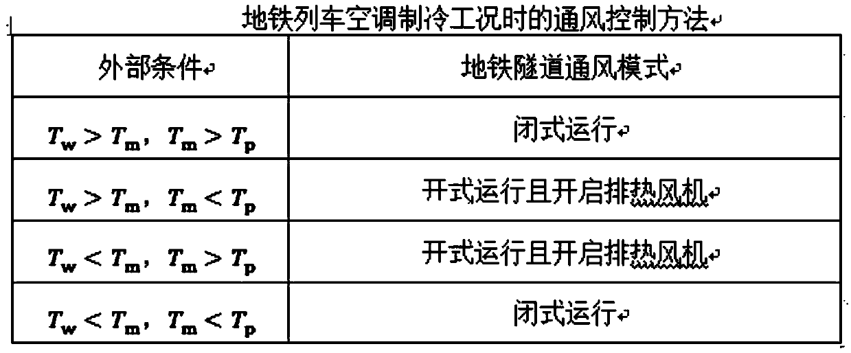
[0084] In this embodiment, on the basis of Embodiment 1, the optimum tunnel air temperature T is calculated. p After the temperature is 22.5℃, the ventilation control method of the subway tunnel is as follows:

[0085] (1) When the subway train is under the condition of air conditioning and air conditioning heating:

[0086] When the outdoor air temperature is higher than the air temperature in the tunnel, the ventilation mode of the subway tunnel is open operation and the heat exhaust fan is turned on;

[0087] When the outdoor air temperature is lower than the air temperature inside the tunnel, the ventilation mode of the subway tunnel is closed operation;

[0088] (2) When the air conditioner in the subway train is in cooling mode:

[0089] When the outdoor air temperature T w is 30°C, the actual air temperature T in the tunnel m is 32°C, then the ventilation mode of the subway tunnel is open operation and the heat exhaust fan is turned on at this time;

[0090] When t...


PUM


Abstract

The invention discloses a method for measuring and calculating the optimal temperature of a subway tunnel with a built-in waste heat recovery device, and based on this, a more reasonable and energy-saving ventilation control method for a subway tunnel is proposed. The tunnel ventilation control method of the built-in waste heat recovery device in the subway tunnel provided by the present invention takes into account the influence of the optimal tunnel air temperature, so that the work of the train air conditioner and the waste heat recovery device is more coordinated, and at the same time, the overall energy consumption of the system is lower.

Description

technical field [0001] The invention relates to the technical field of transportation infrastructure, in particular to a ventilation control method for subway tunnels. Background technique [0002] Nowadays, the subway has become one of the important tools for people to travel. The subway ventilation system can better update the air in the tunnel and increase the comfort of passengers. Today, the subway tunnel ventilation control method only considers the air temperature in the subway tunnel, the natural temperature of the local strata and The outside air temperature is three factors. [0003] The main factors considered in the existing subway tunnel ventilation control methods are: ① the air temperature in the subway tunnel; ② the outdoor air temperature, and ③ the natural temperature of the local formation. [0004] The above ventilation control method does not consider the influence of the optimal air temperature in the tunnel when the waste heat recovery device is built...

Claims


Application Information

Patent Timeline
Patent Type & Authority Patents(China)
IPC IPC(8): E21F1/00E21F17/18
CPCE21F1/003E21F17/18
Inventor 孙婷婷刘艳峰刘雄韩玚邵先来柴永金
Owner XI'AN UNIVERSITY OF ARCHITECTURE AND TECHNOLOGY
Learn More