Braking device of fuel pressure control braking valve

A fuel pressure and braking device technology, applied in the direction of valve devices, engine components, machines/engines, etc., can solve the problems of insufficient pressure, decompression braking timeliness and insufficient stability, etc., to achieve rapid response, fast control, good stability effect

Active Publication Date: 2017-06-20
JILIN UNIV
View PDF8 Cites 3 Cited by
  • Summary
  • Abstract
  • Description
  • Claims
  • Application Information

AI Technical Summary

Problems solved by technology

[0005] In order to solve the problem that the pressure of the brake valve controlled by compressing the lubricating oil is insufficient during the decompression braking of the existing engine, resulting in insufficient timeliness and stability of the decompression braking, the present invention provides a fuel pressure control brake valve Braking device

Method used


Image

  • Braking device of fuel pressure control braking valve
  • Braking device of fuel pressure control braking valve
  • Braking device of fuel pressure control braking valve

Examples


Embodiment Construction

[0022] Describe technical scheme of the present invention in detail below in conjunction with accompanying drawing:

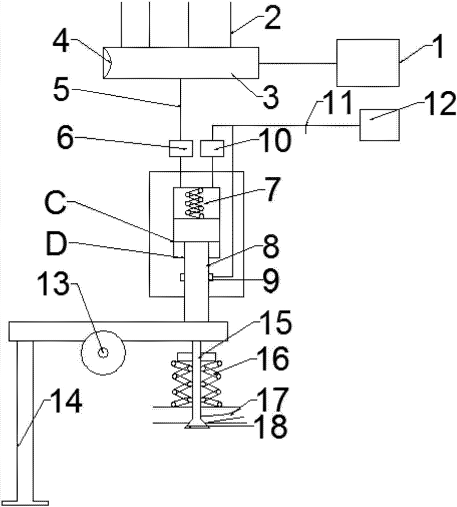
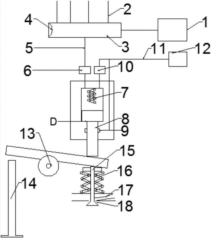
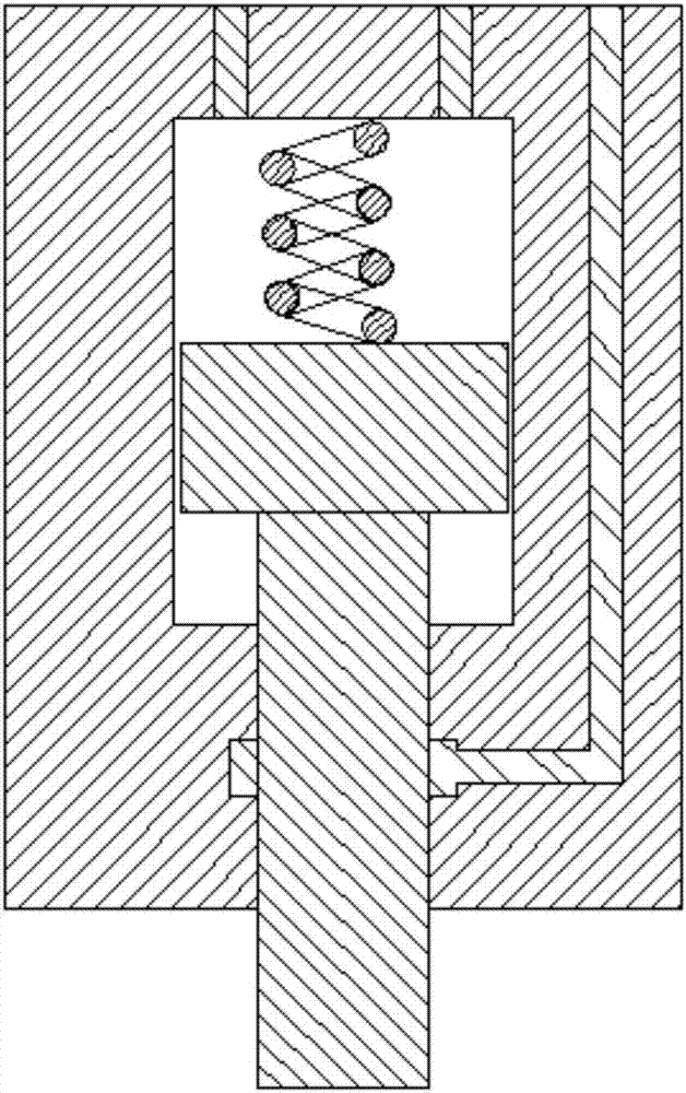
[0023] refer to figure 1 , a brake device for a fuel pressure control brake valve, comprising an oil pump 1, a fuel injection pipe 2, a high-pressure fuel rail 3, a pressure sensor 4, an oil outlet pipe 5, an oil inlet solenoid valve 6, a plunger spring 7, and a plunger coupler Part 8, low-pressure ring groove 9, drain solenoid valve 10, low-pressure oil circuit 11, fuel tank 12, rocker arm 13, tappet 14, valve tappet 15, valve spring 16, exhaust passage 17, exhaust valve 18.

[0024] The oil pump 1 communicates with the high-pressure oil rail 3, and the high-pressure oil rail 3 is provided with an oil injection pipe 2. The high-pressure oil rail 3 communicates with the cavity in the plunger pair 8 through the oil outlet pipe 5 . The fuel tank 12 communicates with the plunger 8 through the low-pressure oil circuit 11, and is used for recovering useless high-p...


PUM


Abstract

The invention discloses a braking device of a fuel pressure control braking valve. The braking device comprises a fuel pump, a high-pressure fuel rail, a pressure sensor, a plunger spring, a plunger and barrel assembly, a low-pressure ring slot, a fuel tank, a swing arm, a tappet and an exhaust valve. The fuel pump communicates with the high-pressure fuel rail, the high-pressure fuel rail communicates with the plunger and barrel assembly through a fuel outflow pipe, the fuel tank communicates with the plunger and barrel assembly through a low-pressure fuel way, the swing arm is located between the plunger and barrel assembly and the tappet, the plunger is located above the same end of the swing arm, and a valve tappet of the exhaust valve is located below the same end of the swing arm. The pressure sensor is arranged at one end of the high-pressure fuel rail, and pressure of fuel in the high-pressure fuel rail is detected in real time. Due to the fact that the pressure of the fuel in the high-pressure fuel rail is high and stable, the timeliness and stability of decompression braking can be improved, meanwhile, the tappet does not need to compress lubricating oil, the tappet does not need to be treated through a special process, and the cost is reduced.

Description

technical field [0001] The invention belongs to the field of engine braking, in particular to a braking device for a fuel pressure control braking valve. Background technique [0002] When driving down a long slope continuously for a long time, in order to prevent the temperature of the brake shoe from rising rapidly due to continuous braking, the braking efficiency will be greatly reduced, and it will be impossible to stop in an emergency, resulting in frequent road traffic safety accidents. It is necessary to increase the auxiliary brake. . [0003] At present, compared with other types of braking technology, engine braking technology is widely used because of its light weight, small size, short response time, compact structure, low price, high braking power and stable braking power. Engine braking technology mainly includes engine exhaust braking and engine decompression braking. [0004] Engine decompression braking is to cut off the fuel after starting the braking dev...

Claims


Application Information

Patent Timeline
Patent Type & Authority Applications(China)
IPC IPC(8): F01L13/06
CPCF01L13/06
Inventor 朱昌吉朱延鑫刘宇曲大伟李君贾江峰
Owner JILIN UNIV
Why Eureka
Try Eureka