Switching circuit

A switching circuit and memory switch technology, applied in electronic switches, electrical components, pulse technology, etc., can solve the problems of switching circuits that are difficult to carry and heavy loads, and achieve the effects of protecting electricity safety, avoiding large-scale transformation, and saving costs

Inactive Publication Date: 2015-03-04
上海丽界智能科技有限公司
View PDF4 Cites 0 Cited by
  • Summary
  • Abstract
  • Description
  • Claims
  • Application Information

AI Technical Summary

Problems solved by technology

[0003] It is difficult for the existing switching circuit to carry a large load without large-scale modification of the existing circuit and the need for a dedicated power supply.

Method used


Image

  • Switching circuit
  • Switching circuit
  • Switching circuit

Examples


Embodiment Construction

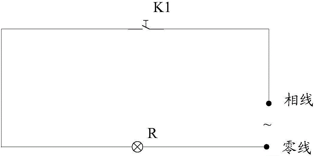
[0027] Since the circuit wiring is usually laid out during the construction of buildings and houses, and the wiring is usually buried inside the wall, only some switch boxes and load connection terminals are leaked. Therefore, in order to facilitate the promotion and application of switching circuits, the newly designed switching circuits should avoid large-scale transformation of existing circuits as much as possible.

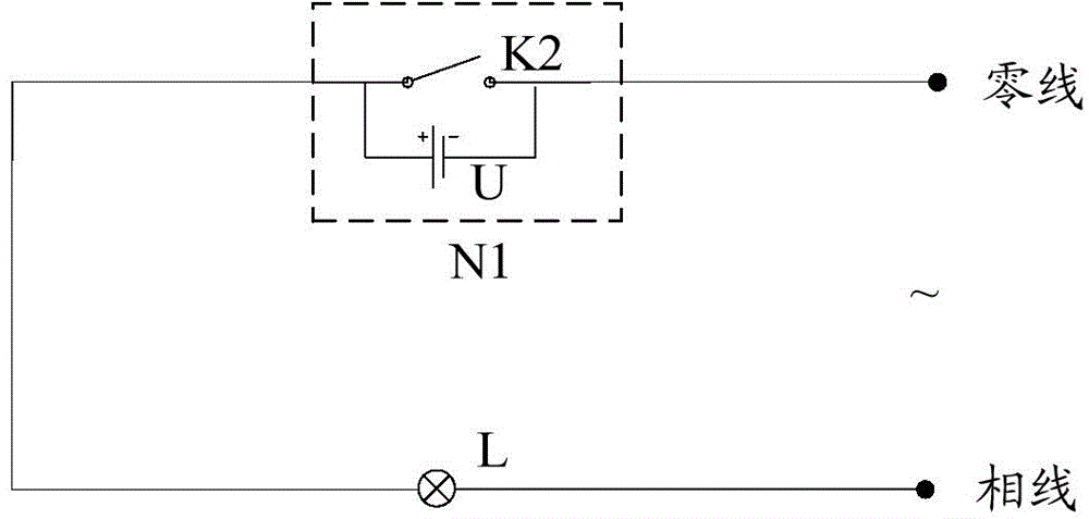
[0028] In the case of avoiding large-scale modification of the existing circuit, in order to realize the remote control function of the switch, such as figure 2 As shown, currently there is a method of setting a rechargeable battery in the switch box N1. When the circuit is powered on and the load L is in the working state, the circuit can charge the battery U, and when the circuit is in the disconnected state, it can pass The battery U supplies power to the wireless switch K2, so that the remote control of the wireless switch K2 can be realized. However, wh...


PUM


Abstract

The invention discloses a switching circuit, which comprises a normally-closed switch and a memory switch, wherein one end of the normally-closed switch is coupled with a first end of the memory switch; the second end of the memory switch is coupled with the first end of a first loader, and the third end of the memory switch is coupled with the second end of the first loader; and the normally-closed switch and the memory switch are also suitable to couple with a second loader. The switching circuit can bear large load under a condition that a traditional circuit is not transformed on a large scale and no independent power supplies are required.

Description

technical field [0001] The invention relates to the technical field of switching circuits, in particular to a switching circuit. Background technique [0002] Traditional mechanical wall switches such as figure 1 , is a simple control form of one on and one off, and most of them are realized on the 86-type cassette. Usually, the control of the switch K1 is realized by manually touching the button on the switch box, and then the circuit is turned on and off. , when the switch K1 is closed, the load R works, and when the switch K1 is open, the load R stops working. [0003] It is difficult for the existing switching circuit to carry a large load without large-scale modification of the existing circuit and without the need for a dedicated power supply. Contents of the invention [0004] The problem solved by the embodiments of the present invention is how to provide a switch circuit capable of carrying a large load without large-scale modification of the existing circuit an...

Claims


Application Information

Patent Timeline
Patent Type & Authority Applications(China)
IPC IPC(8): H03K17/94
Inventor 王政
Owner 上海丽界智能科技有限公司
Why Eureka
Try Eureka