Continuous trajectory control method for 3-degree of freedom pneumatic manipulator

A pneumatic manipulator and trajectory control technology, applied in the field of manipulators, can solve the problems of unstable friction, easy overshoot, phase delay, etc., and achieve the effects of large driving power, high cost performance and simple structure

Inactive Publication Date: 2017-03-29
于平
View PDF0 Cites 2 Cited by
  • Summary
  • Abstract
  • Description
  • Claims
  • Application Information

AI Technical Summary

Problems solved by technology

Pneumatic proportional / servo position control system, due to its poor rigidity, uncertain friction, etc., makes the pneumatic proportional Dong clothing control system prone to overshoot, phase delay, etc. during the control process, especially crawling when running at low speed

Method used


Image

  • Continuous trajectory control method for 3-degree of freedom pneumatic manipulator
  • Continuous trajectory control method for 3-degree of freedom pneumatic manipulator
  • Continuous trajectory control method for 3-degree of freedom pneumatic manipulator

Examples


Embodiment Construction

[0015] The present invention will be further described below with reference to the drawings and embodiments.

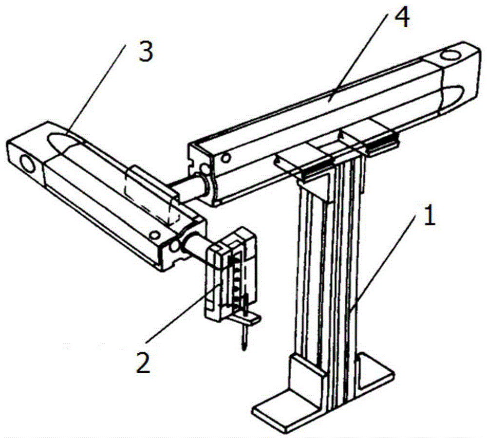
[0016] Such as figure 1 , The 3-degree-of-freedom pneumatic proportional Dongfu manipulator adopts a rectangular coordinate structure. The mechanism is composed of a support, a z-axis module, a y-axis module and a z-axis module. The integrated module with standard mechanical and electronic interfaces is adopted, which can improve The reliability of the system, on the other hand, can quickly form a manipulator system to reduce the cost of pneumatic manipulators.

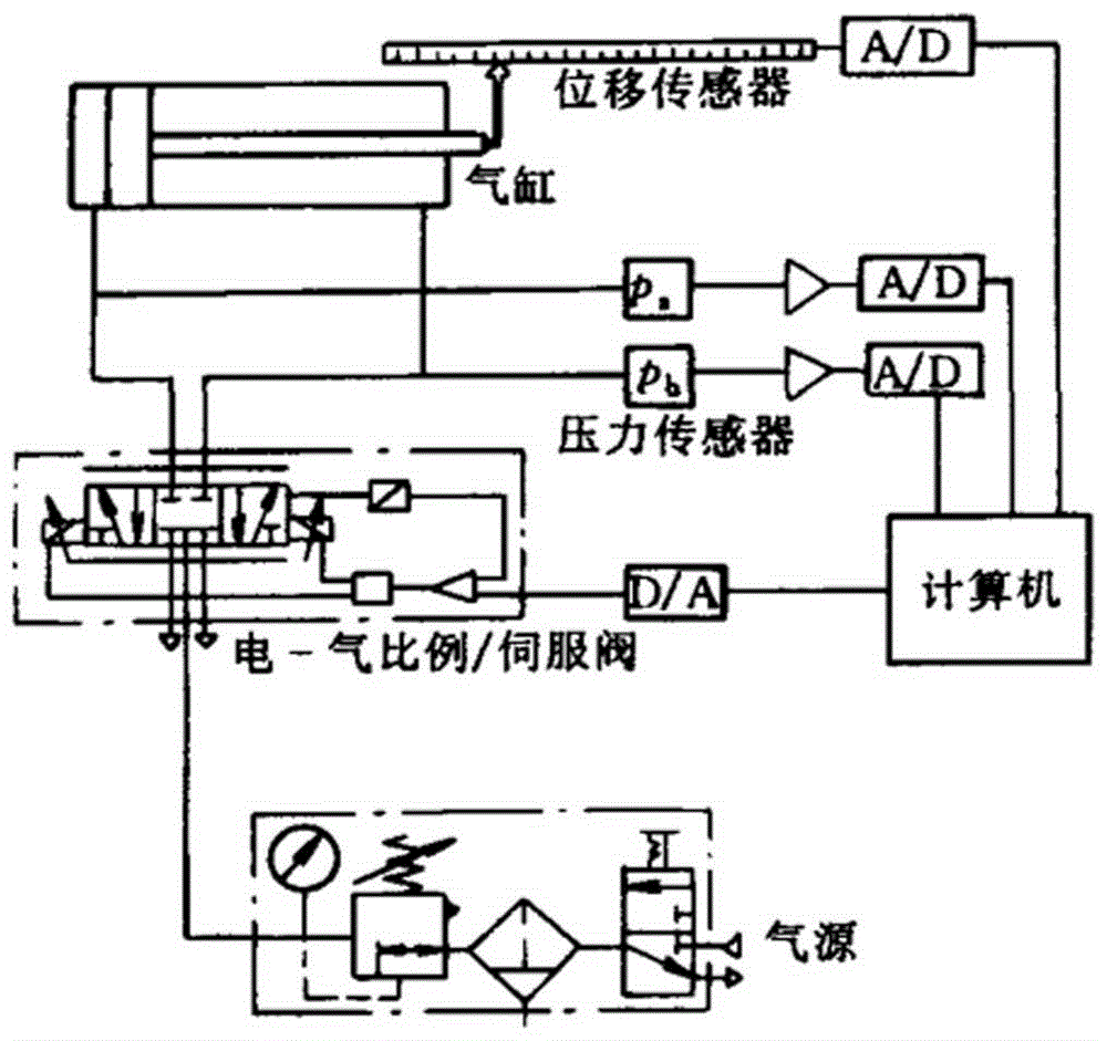
[0017] Such as figure 2 In the control system, the computer detects the pressure of the two chambers of the cylinder and the displacement of the cylinder piston through A / D. The computer passes through a certain algorithm according to the given signal and feedback signal, and outputs the signal through D / A to the electric-pneumatic proportional servo valve to achieve closed-loop control. .

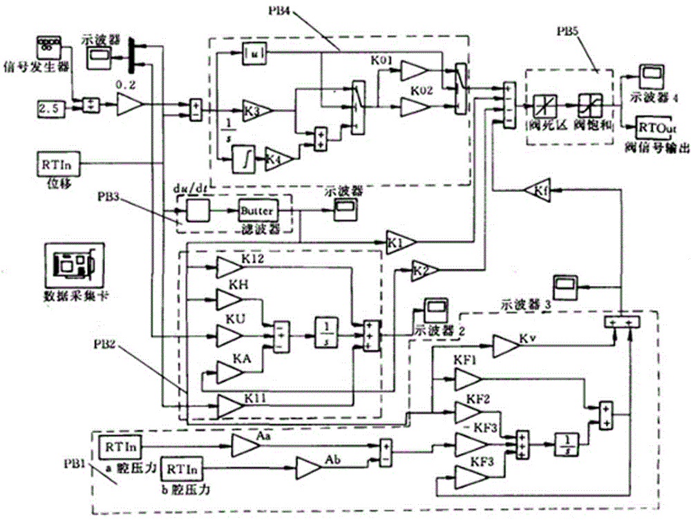
[0018] Such as image ...


PUM


Abstract

Provided is a continuous trajectory control method for a 3-degree of freedom pneumatic manipulator. The method is characterized in that a proper control strategy is adopted; a pneumatic proportion/servo position system can compensate for defects such as poor rigidity, and poor resistance to external interference and achieves a trajectory tracking feature; the system can also be compared with an expensive motor-servo system; the pneumatic proportion/servo position control system utilizes features such as simple structure, high driving power, high control precision, and high cost performance so that an excellent application prospect in the industrial automation field is obtained.

Description

Technical field [0001] The invention relates to a manipulator, in particular to a continuous trajectory control method for a 3-degree-of-freedom pneumatic manipulator. Background technique [0002] Pneumatic servo control technology was used in the aerospace field in the late 1950s. At that time, British Shearer and others first used it in the attitude and flight stability control system of space vehicles and missiles. Most of the early pneumatic proportional Dongfu systems used mechanical control. Pneumatic proportional / servo position control system, due to its poor rigidity, variable friction and other reasons, the pneumatic proportional servo control system is prone to overshoot and phase delay during the control process, especially crawling when running at low speeds. . With the rapid development of microelectronics technology, microelectronics technology has been introduced into pneumatic servo system, pneumatic servo control technology, and more precisely the electric-pne...

Claims


Application Information

Patent Timeline
Patent Type & Authority Applications(China)
IPC IPC(8): B25J9/16
CPCB25J9/161
Inventor 于平
Owner 于平
Why Eureka
Try Eureka