
Servo Control Method of Gasoline Engine Speed ​​in Legged Robot Hydraulic System

A gasoline engine and hydraulic system technology, applied in engine control, machine/engine, electrical control, etc., can solve problems such as increased assembly difficulty, complicated speed measurement, and inability to meet high-power engine speed control, reducing the difficulty of mechanical assembly and ensuring The effect of rotational speed stability, good dynamic and static performance

Active Publication Date: 2019-06-21
SHANDONG UNIV
View PDF4 Cites 0 Cited by
  • Summary
  • Abstract
  • Description
  • Claims
  • Application Information

AI Technical Summary

Problems solved by technology

[0005] The controller of the above system controls the start and stop of the engine and the connection or disconnection of the oil port of the reversing valve of the hydraulic system through signals. The working condition of the monitoring system, but after the flow demand of the robot system increases, a higher-power engine needs to be replaced. The original control method cannot meet the speed control of a high-power engine; and the speed measurement is complicated, and the output shaft of the engine needs to be modified. , increasing the difficulty of assembly

Method used


Image

  • Servo Control Method of Gasoline Engine Speed ​​in Legged Robot Hydraulic System
  • Servo Control Method of Gasoline Engine Speed ​​in Legged Robot Hydraulic System
  • Servo Control Method of Gasoline Engine Speed ​​in Legged Robot Hydraulic System

Examples


Embodiment Construction

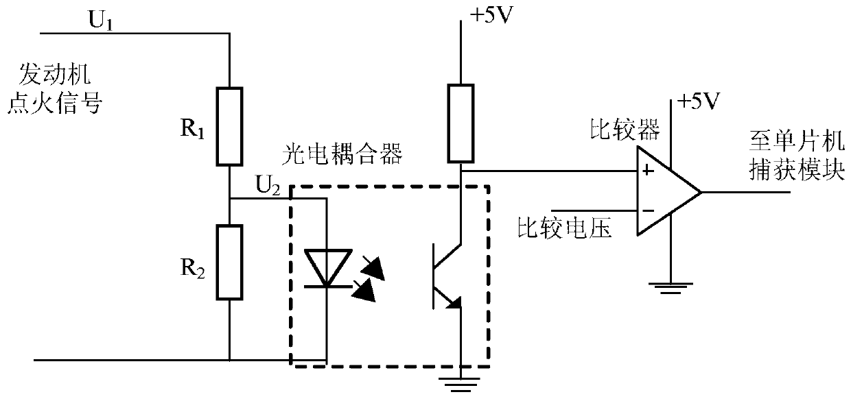
[0040] The speed servo control method of the gasoline engine of the leg-foot type robot hydraulic system of the present invention adopts a speed measuring circuit such as figure 1 As shown, the method of directly using the engine ignition signal to measure the engine speed is adopted. Since the initial signal peak-to-peak value is about 100V, it needs to be controlled by R 1 and R 2 The resistor divider network formed in series is used for step-down processing, and the processed voltage U 2 =U 1 *R 2 / (R 1 +R 2); after passing through the photocoupler, the signal is converted into a DC signal by using its one-way pass characteristic; finally, after the comparator LM393 is compared with the comparison voltage, the output square wave waveform with an amplitude of 5V is captured and calculated by the microcontroller capture module Speed, the calculation formula is v fed =60*f, where f is the frequency of the square wave captured by the single chip microcomputer.

[0041] ...


PUM


Abstract

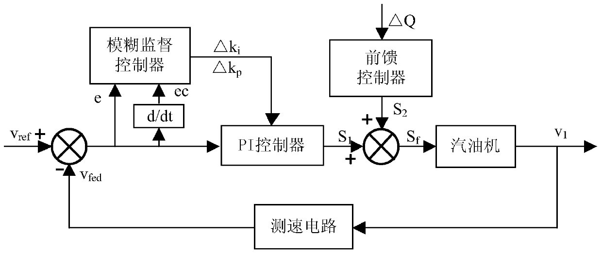
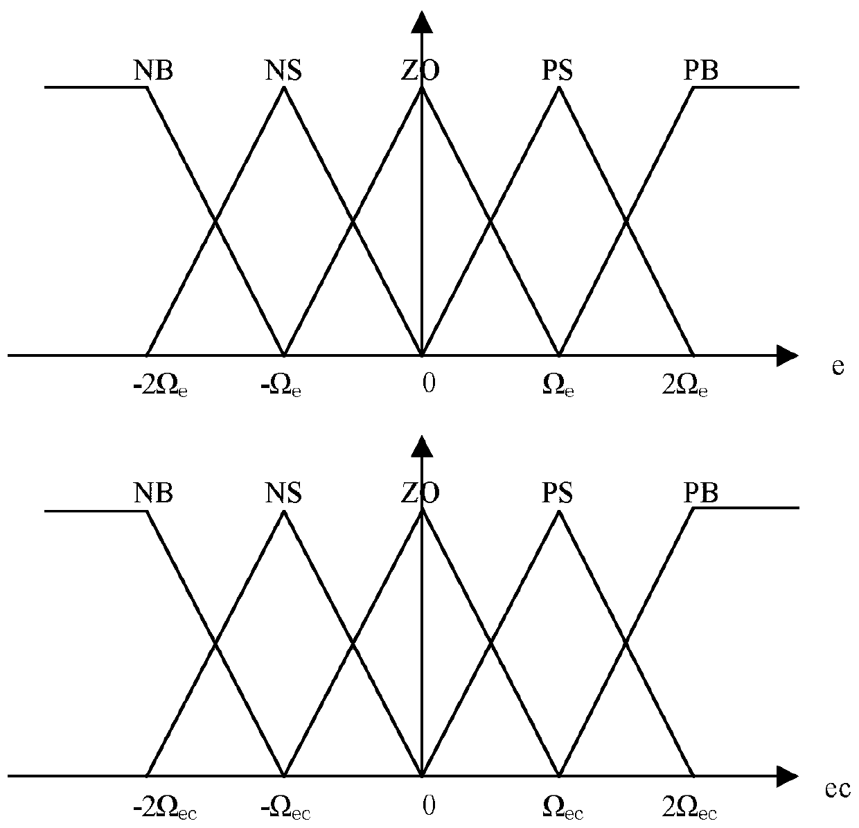
The invention provides a servo control method for the gasoline engine speed in a hydraulic system of a legged robot. The servo control method comprises the following steps: (1) calculating the engine speed error e and the engine speed error change rate ec; (2), after the fuzzy logic calculation of e and ec, outputting the proportionality coefficient increment delta kp and the integral coefficient increment delta ki; (3) calculating the proportionality coefficient and the integral coefficient according to the following formulas correspondingly: kp = kp0 + delta kp and ki = ki0 + delta ki; (4) calculating the accelerator opening degree according to the following formula: S1 = S1_old + kp*ec + ki*e; (5) calculating the accelerator opening degree change caused by the hydraulic oil flow rate change according to the following formula: S2 = kQ*detal Q; and (6) calculating the final accelerator opening degree Sf = S1 + S2, wherein the rotation of a steering engine is controlled through the accelerator opening degree in the PWM form, the air inlet volume is controlled by controlling the opening degree of an engine throttle valve through an accelerator cable, and finally the engine speed is controlled. The servo control method provided by the invention has the advantages that the feedforward control is adopted, so that the stable engine speed can be guaranteed well under the circumstance that the flow rate changes suddenly; parameters are modified online by adoption of fuzzy self-tuning, so that the different control requirements can be met; and accordingly, the hydraulic system can have the good dynamic property and static property.

Description

technical field [0001] The invention relates to a gasoline engine rotation speed servo control method for a hydraulic leg-foot robot, belonging to the technical field of gasoline engine-driven hydraulic system control. Background technique [0002] In the driving mode of legged robots, it is necessary to ensure the high dynamics and load capacity of the robot, so the power source of its onboard hydraulic system should have a high energy density. Although electric drive has advantages such as low noise, its disadvantages such as poor battery life and slow battery charging affect its application in the field of legged robots. Gasoline engines have higher efficiency, smaller volume and lower weight, which facilitates the realization of robot energy. The system is airborne, so the hydraulic system driven by the engine is an ideal solution for the legged robot drive system. The power of the hydraulic system of the robot is provided by the gasoline engine, which drives the variab...

Claims


Application Information

Patent Timeline
Patent Type & Authority Patents(China)
IPC IPC(8): F02D29/04F02D41/00F02D41/14
CPCF02D29/04F02D31/002F02D31/007F02D41/0002F02D41/0097F02D41/1404F02D2041/1409F02D2041/141
Inventor 李贻斌杨琨柴汇马昕田国会李彬
Owner SHANDONG UNIV
Learn More