Mechanical splice

A technology of mechanical joints and steps, applied in the direction of mechanical equipment, pipes/pipe joints/fittings, sealing surface connections, etc., can solve leakage, mechanical joint jackets have no anti-off structure, and the degree of connection firmness cannot adapt to higher pressure occasions, etc. problems, to achieve the effect of increasing service life, saving material consumption, and reducing overall weight

Inactive Publication Date: 2017-06-20
TIANJIN SINO SWISS BONLOK PIPE CONNECTION TECH
View PDF10 Cites 1 Cited by
  • Summary
  • Abstract
  • Description
  • Claims
  • Application Information

AI Technical Summary

Problems solved by technology

[0002] The existing mechanical joint jacket and the main body have no anti-off structure, and the outer surface of the bush has no teeth, so the connection is not firm enough to adapt to high pressure occasions, and leakage will occur when the medium pressure exceeds 10 MPa

Method used


Image

  • Mechanical splice
  • Mechanical splice
  • Mechanical splice

Examples


Embodiment Construction

[0026] The solutions of the present invention will be described in detail below in conjunction with the drawings and specific embodiments.

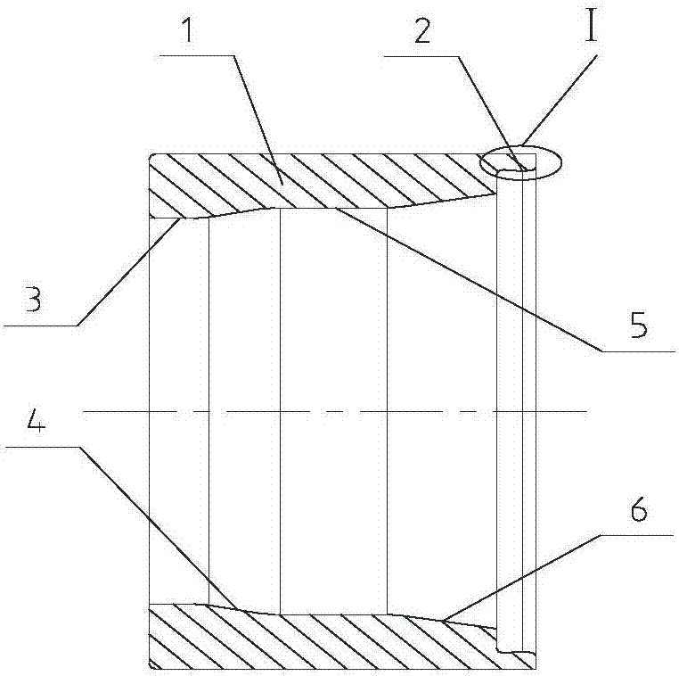
[0027] Such as figure 1 As shown, the inner hole of the jacket 1 from the small end to the large end is cylindrical surface 1 3, conical surface 1 4, cylindrical surface 2 5, conical surface 2 6, and anti-off ring 2;

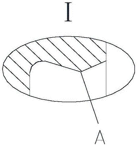
[0028] Such as figure 2 As shown, the anti-off ring is an annular protrusion with a triangular cross-section, and A is the raised apex of the annular protrusion, which is the smallest inner diameter on the anti-off ring;

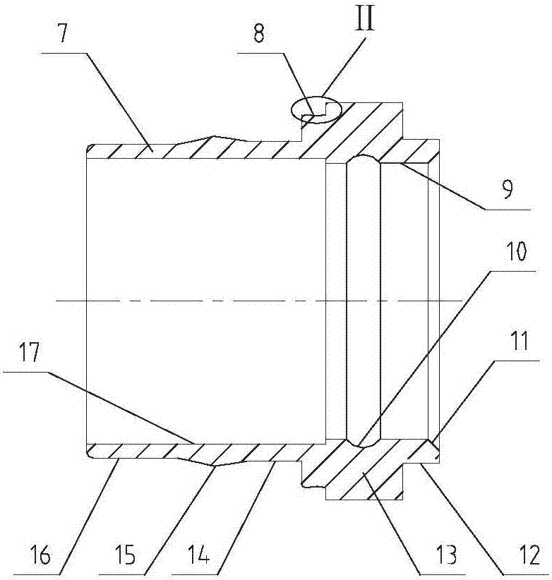
[0029] Such as image 3 As shown, the main body 7 shaft shoulder 13 is provided with an anti-off groove 8, and the outer circumference of the main body is sequentially provided with a stepped outer circle 12, a shaft shoulder 13, a stepped outer circle 2 14, and a stepped outer circle 3 16, and a stepped outer circle 2 14 is in contact with the stepped outer circle 3 16, which is an arc-shaped protrus...


PUM


Abstract

The invention discloses a mechanical splice comprising two main bodies, two sleeves and a bushing, wherein the bushing is arranged in the bore of the two main bodies arranged symmetrically, and the two sleeves are sheathed on the periphery of the main bodies; a stepped excircle I, a shaft shoulder, a stepped excircle II and a stepped excircle III are arranged on the periphery of the main bodies in turn from front to back, and the shaft shoulder is raised and annular, and is provided with a triangular, concave and annular drop-proof slot; a cylindrical surface I, a conical surface I, a cylindrical surface II, a conical surface II and a drop-proof ring are arranged in the bores of the sleeves from small ends to big ends in turn, the bushing is cylindrical, the middle part is thick and both sides are thin; the middle of the outside surface of the bushing is provided with a triangular annular bulge. The diameter, volume and weight of the mechanical splice disclosed by the invention are reduced obviously, so that the space occupation and total weight of a pipeline system are reduced, which is especially important for those aviation and aerospace fields with high requirements for the volume and weight.

Description

technical field [0001] The invention belongs to the technical field of pipeline connection, and more specifically relates to a mechanical joint. Background technique [0002] The existing mechanical joint jacket and main body have no detachment prevention structure, and the outer surface of the bush has no teeth, so the connection is not firm enough to adapt to higher pressure occasions, and leakage will occur when the medium pressure exceeds 10 MPa. Contents of the invention [0003] The object of the present invention is to overcome the shortcomings of the above-mentioned prior art, and provide a mechanical joint with high pressure resistance that exceeds the existing joints. [0004] The technical solution adopted by the mechanical joint of the present invention is to include two main bodies, two jackets and a bushing, the bushing is arranged in two symmetrically arranged inner holes of the main body, and the two jackets are respectively put on the outer periphery of th...

Claims


Application Information

Patent Timeline
Patent Type & Authority Applications(China)
IPC IPC(8): F16L19/10
CPCF16L19/103
Inventor 高迪·海尔纳
Owner TIANJIN SINO SWISS BONLOK PIPE CONNECTION TECH
Why Eureka
Try Eureka