Limited measuring point based air conditioning system performance online detection method

A technology of an air conditioning system and a detection method, which is applied to heating and ventilation control systems, heating and ventilation safety systems, heating methods, etc. Effect

Inactive Publication Date: 2017-06-20
SHANGHAI KELING ENERGY TECH
7 Cites 27 Cited by

AI-Extracted Technical Summary

Problems solved by technology

[0003] The present invention aims at the defect that the existing technology cannot measure the relevant performance parameters such as the refrigerant flow rate through the temperature and pressure measuring points at the inlet and outlet of the compressor, so the performance parameters of the system cannot be accurately obtained, and proposes an air-conditioning system performance...

Method used

[0058] Step 4, based on the fan performance curve and the fan resistance-heat exchanger characteristic equation, the air volume of the indoor ...

Abstract

The invention discloses a limited measuring point based air conditioning system performance online detection method. Measuring points are arranged in an operating air conditioning system to record measuring point parameters in real time, and the refrigerant flow of the air conditioning system is obtained through compressor flow fitting calculation; and heat exchange amount calculation of a condenser and an evaporator is carried out in combination with a refrigerating cycle theory, the actual refrigerating capacity, the compressor actual power and the real-time EER (energy efficiency ratio) of the air conditioning system are obtained, the air volumes and pressure drop of an indoor unit and an outdoor unit are obtained through calculation based on a fan performance curve and a fan resistance-heat exchanger characteristic equation, and online detection on the performance of the air conditioning system is achieved. According to the method, design is reasonable, work is reliable, and the operating air conditioning system can be monitored online in real time without demounting instruments.

Application Domain

Technology Topic

Traffic volumePerformance curves +9

Image

  • Limited measuring point based air conditioning system performance online detection method
  • Limited measuring point based air conditioning system performance online detection method
  • Limited measuring point based air conditioning system performance online detection method

Examples

  • Experimental program(1)

Example Embodiment

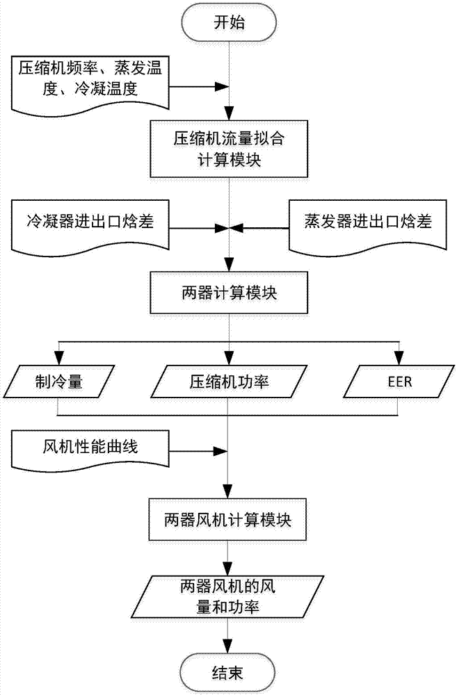
[0032] Such as figure 1 As shown, this embodiment includes the following steps:
[0033] Step 1. Arrange measuring points in the running air conditioning system, and record the measuring point parameters in real time.
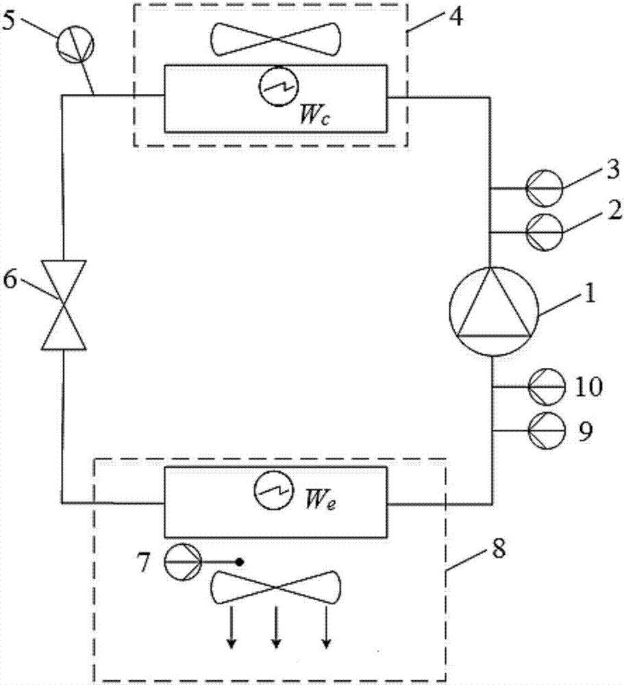
[0034] Such as figure 2 As shown, the arrangement of measuring points refers to the arrangement of compressor discharge temperature measuring points and compressor discharge pressure measuring points between the compressor and condenser of the air conditioning system, and the compressor discharge temperature parameter T 0 And the exhaust pressure parameter p 0; Arrange the temperature measurement point of the liquid pipe at the outlet of the condenser liquid pipe to obtain the liquid pipe temperature parameter T 2; Arrange the compressor suction temperature measuring point and compressor suction pressure measuring point between the evaporator and the compressor, and obtain the suction temperature parameter T of the compressor respectively 1 And the suction pressure parameter p 1; Arrange the return air temperature measurement points of the evaporator fan on the return air side of the evaporator fan to obtain the return air temperature parameter T r.
[0035] An expansion valve is arranged between the condenser and the evaporator.
[0036] The evaporator and condenser are respectively provided with an evaporator fan power meter and a condenser fan power meter to record the evaporator fan power W e And condenser fan power W c.
[0037] Step 2. Perform compressor flow fitting calculation through the compressor flow fitting calculation module according to the parameters obtained in step 1, to obtain the refrigerant flow of the air conditioning system.
[0038] The described compressor flow fitting calculation refers to: using the compressor theoretical calculation formula fitted by the compressor performance parameters, the compressor flow rate at any frequency is converted into a polynomial form about the inlet and outlet pressure and other parameters with the theoretical model. , A series of data points are obtained through the 10-coefficient model provided by the compressor manufacturer, and the coefficients in the polynomial can be fitted to calculate the refrigerant flow rate.
[0039] The compressor is an inverter compressor.
[0040] The refrigerant flow rate m is: Where: C 0 ~C 3 Is the coefficient to be fitted, Is the cylinder volume, v i Is the inspiratory specific volume, f x Is the compressor frequency, p i Is the suction pressure of the compressor.
[0041] The compressor inlet pressure p i , Compressor outlet pressure p o , Cylinder volume Inspiratory specific volume v i And frequency f x A known.
[0042] According to the 10 coefficient formula obtained from the standard test experiment of the compressor, a series of flow data at different evaporating temperature, condensing temperature and frequency can be obtained. According to the above formula, the least square method can be fitted to obtain C 0 ~C 3.
[0043] Step 3. Combining the theory of refrigeration cycle, the cooling capacity of the air conditioning system, the heat exchange of the condenser, the compressor power and the EER (energy efficiency ratio) are calculated through the two-unit calculation module.
[0044] The refrigeration cycle theory refers to the calculation of the heat exchange on the refrigerant side of the air conditioning system (that is, the theoretical refrigeration capacity) according to the refrigerant flow rate and the enthalpy value at the inlet and outlet of the evaporator, and the heat exchange of the condenser is calculated in the same way. In this case, heat loss needs to be considered before calculating the actual cooling capacity; due to the energy conservation of the air conditioning system, the actual power of the compressor can be calculated according to the actual cooling capacity, condenser heat exchange and heat loss to obtain the real-time EER of the air conditioning system.
[0045] This embodiment is a special case, that is, the compressor is arranged near the evaporator, and the compressor will dissipate part of the cold energy on the air side of the evaporator.
[0046] The said refrigerant side heat exchange Q eva For: Q eva =m×(h 1 -h 4 ), where: h 1 Is the enthalpy value of the evaporator outlet, h 4 Is the enthalpy value of the evaporator inlet.
[0047] Such as image 3 As shown, point A is the evaporator outlet, point B is the condenser inlet, point C is the condenser outlet, point D is the evaporator inlet, and the corresponding enthalpy values ​​are respectively h 1 , H 2 , H 3 And h 4.
[0048] According to the physical property calculation formula, the temperature and pressure of a point can be used to calculate the enthalpy value of that point. And the pressure p at point A and point B 1 , P 2 And temperature T 1 , T 2 Known, the enthalpy h of point A and point B can be obtained 1 , H 2; Temperature T at point C 3 It is known that the pressure at point C is the same as that at point B, and the enthalpy value of point D is h 4 Same as point C.
[0049] The amount of heat exchange on the refrigerant side obtained from the above equation is the theoretical cooling capacity, and the heat loss caused by the heat exchange between the compressor next to the evaporator and the surrounding air needs to be considered. Therefore, the theoretical cooling capacity is corrected to obtain the actual cooling capacity.
[0050] The actual cooling capacity is: Q real =Q eva -Q loss , Where: Q loss Is the heat loss (dissipated amount).
[0051] Said heat loss Q loss for: Among them: h is the heat transfer coefficient, d is the outer diameter of the compressor, L is the length of the compressor, R is the fan opening (%), R bass Is the reference opening of the fan during the test, T r Is the return air temperature of the evaporator.
[0052] The heat transfer coefficient h is usually 50.
[0053] The fan opening R is directly read out by the fan meter.
[0054] The said condenser heat exchange Q cond For: Q cond =m×(h 2 (p 2 ,T 2 )-h 3 (p 2 ,T 3 )).
[0055] The actual power of the compressor can be analyzed and calculated by the energy conservation of the air conditioning system.
[0056] The actual power of the compressor is: W real =W ceff +Q loss , Where: W real Is the actual compressor power, W ceff Is the theoretical power of the compressor, W ceff =Q cond -Q eva.
[0057] The energy efficiency ratio is:
[0058] Step 4. Based on the fan performance curve and the fan resistance-heat exchanger characteristic equation, the air volume of the indoor and outdoor units is calculated through the fan calculation module to realize the online detection of the air conditioning system performance.
[0059] The calculation based on the fan performance curve and the fan resistance-heat exchanger characteristic equation means: According to the fan performance curve relationship (Pq-Power) provided by the fan manufacturer, the pressure drop and air volume of the fan at a given power can be obtained The first relationship; combining the air-side resistance characteristic equation of the heat exchanger (condenser and evaporator) and the relationship between air volume and wind speed, the second relationship between the pressure drop on the air side of the heat exchanger and the air volume can be obtained; two Relations are solved simultaneously to obtain the air volume and pressure drop at a given fan power.
[0060] The fan performance curve is: ΔP=f(q,P), where: ΔP is the pressure drop, q is the air volume, and P is the fan power.
[0061] The derivation process of the second relationship is as follows: the air-side pressure drop of the indoor and outdoor units of the air conditioning system has a quadratic relationship with the wind speed, and there is a linear relationship between the wind speed and the air volume, namely: Among them: g is the acceleration due to gravity, A is the area of ​​the windward side of the heat exchanger, L and d are the inherent (known) parameters of the heat exchanger. Substituting the test operating point data of the heat exchanger and the relationship between wind speed and air volume, we can get: ΔP=kq 2 , Where: k is the resistance characteristic coefficient of the heat exchanger, that is, the product of all constant terms.
[0062] The air volume q and pressure drop ΔP under a given fan power are: When the fan power P is known, the simultaneous equation is a two-dimensional quadratic equation, which can be solved to obtain the only real root of pressure drop and air volume.
[0063] There is a linear relationship between the fan power P and the fan opening R, namely: P=aR+b, where a and b are coefficients to be fitted.
[0064] The relationship between the fan opening R and the pressure drop ΔP is: ΔP=f(R).
[0065] The relationship between the fan opening R and the air volume q is: q=f(R).
[0066] The above specific implementations can be locally adjusted by those skilled in the art in different ways without departing from the principle and purpose of the present invention. The protection scope of the present invention is subject to the claims and is not limited by the above specific implementations. All implementation schemes within the scope are bound by the present invention.

PUM

no PUM

Description & Claims & Application Information

We can also present the details of the Description, Claims and Application information to help users get a comprehensive understanding of the technical details of the patent, such as background art, summary of invention, brief description of drawings, description of embodiments, and other original content. On the other hand, users can also determine the specific scope of protection of the technology through the list of claims; as well as understand the changes in the life cycle of the technology with the presentation of the patent timeline. Login to view more.

Similar technology patents

Low-complexity load balancing route algorithm based on LEO satellite network

InactiveCN105227483AGood performance indexReasonable designNetwork topologiesData switching networksLink designTime complexity
Owner:BEIJING INST OF SPACECRAFT SYST ENG

Classification and recommendation of technical efficacy words

Why Eureka
Try Eureka