System and method for carrying out phase calibration

A phase calibration and phase technology, which is used in direction finders using radio waves, monitoring/testing of radio wave directors, and components of radio wave directors, etc., can solve the problems of low calibration accuracy and low universality, etc. Achieve the effect of high calibration accuracy

Active Publication Date: 2017-06-20
SICHUAN JIUZHOU ELECTRIC GROUP
View PDF5 Cites 15 Cited by
  • Summary
  • Abstract
  • Description
  • Claims
  • Application Information

AI Technical Summary

Problems solved by technology

[0006] The embodiment of the present application provides a system and method for phase calibration, which is used to solve the technical problems of low universality and low calibration accuracy in the phase calibration method in the prior art, and realize the calibration without adding special antenna conditions. The technical effect of providing a system and method that is convenient and practical, has high calibration accuracy and can perform dynamic calibration in real time

Method used


Image

  • System and method for carrying out phase calibration
  • System and method for carrying out phase calibration
  • System and method for carrying out phase calibration

Examples


Embodiment 1

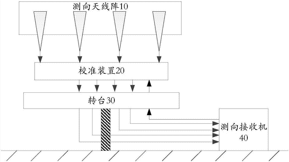
[0056] Please refer to figure 1 , which is a schematic structural diagram of a system for performing phase calibration provided in Embodiment 1 of the present application, and the system includes:

[0057] direction finding antenna array 10;

[0058] The calibration device 20 includes an input terminal and an output terminal, and the input terminal is connected to the direction finding antenna array 10;

[0059] The turntable 30 includes a first end and a second end, the first end is connected to the output end;

[0060] The direction-finding receiver 40 includes an internal channel of the direction-finding receiver and a direction-finding receiver processor, and the direction-finding receiver 40 is connected to the second end;

[0061] Wherein, when phase calibration is required, the calibration device 20 is controlled by the direction-finding receiver 40 to transmit a radio frequency calibration signal, which is sent to the processor of the direction-finding receiver throu...

Embodiment 2

[0075] Based on the same inventive concept as Embodiment 1 of this application, please refer to Figure 4 , which is a flowchart of a method for phase calibration provided in Embodiment 2 of the present application. The method is applied to the system described in Embodiment 1 of the present application, including:

[0076] S101: The calibration device sends a radio frequency calibration signal after receiving the calibration control signal;

[0077]S102: The direction-finding receiver receives the radio frequency calibration signal through the turntable and the internal channel of the direction-finding receiver, wherein the internal channel of the direction-finding receiver includes N receiving channels, and N is an integer greater than or equal to 2;

[0078] S103: The direction finding receiver acquires a phase value corresponding to the radio frequency calibration signal received by each of the N receiving channels;

[0079] S104: The direction-finding receiver determines...


PUM


Abstract

The invention discloses a system and method for carrying out phase calibration. The system is composed of a direction-finding antenna array, a calibration device, a rotary table, and a direction-finding receiver. The calibration device consists of an input terminal and an output terminal; and the input terminal is connected with the direction-finding antenna array. The rotary table includes a first end and a second end; and the first end is connected with the output terminal. The direction-finding receiver includes a direction-finding receiver internal channel and a direction-finding receiver processor; and the direction-finding receiver processor is connected with the second end. The calibration device is controlled by the direction-finding receiver to transmit a radio-frequency calibration signal; the signal passes through the rotary table and the direction-finding receiver internal channel and then is sent to the direction-finding receiver processor; the direction-finding receiver processor carries out phase measurement on the radio-frequency calibration signal; phase adaption errors between receiving channels except the direction-finding antenna array among the receiving channels in the system are obtained, so that phase calibration of the receiving channels except the direction-finding antenna array can be completed based on the phase adaption errors.

Description

technical field [0001] The invention relates to the field of radio technology, in particular to a system and method for phase calibration. Background technique [0002] Phase interferometer direction finding technology has the advantages of high direction finding accuracy, wide instantaneous direction finding range, fast direction finding speed, passive direction finding, etc., and is widely used in the field of radio monitoring. The phase interferometer direction-finding system separates multiple direction-finding antennas in space, receives the radiation source signal and enters the multi-channel direction-finding receiver through its own receiving channel, and extracts the phase difference of the output signal between the receiving channels in the receiver. Finally, the orientation of the radiation source is solved. [0003] The vehicle-mounted interferometer direction-finding system consists of external equipment (including direction-finding antenna, feeder, and radio f...

Claims


Application Information

Patent Timeline
Patent Type & Authority Applications(China)
IPC IPC(8): G01S3/02G01S3/12
CPCG01S3/023G01S3/12
Inventor 先登飞颜伏虎
Owner SICHUAN JIUZHOU ELECTRIC GROUP
Why Eureka
Try Eureka