Novel parker control system based on CAN bus

A CAN bus and control system technology, applied in the field of machinery, can solve the problems of a large number of cables, long control drive lines, increased construction difficulty and workload, etc., and achieve the goals of saving cables, strong real-time performance, and reducing construction difficulty and workload Effect

Inactive Publication Date: 2017-06-20
韩会义
View PDF0 Cites 3 Cited by
  • Summary
  • Abstract
  • Description
  • Claims
  • Application Information

AI Technical Summary

Problems solved by technology

The common point of these three control methods is that the drive circuit performs the braking or release operation of the parking device through the relay in the tail signal building, and the control drive line is too long; the detection signals are also sent to the tail signal building through cables for collection. Requires a large number of cables, while increasing construction difficulty and workload

Method used


Image

  • Novel parker control system based on CAN bus
  • Novel parker control system based on CAN bus
  • Novel parker control system based on CAN bus

Examples


Embodiment Construction

[0020] The present invention will be further described below in conjunction with drawings and embodiments.

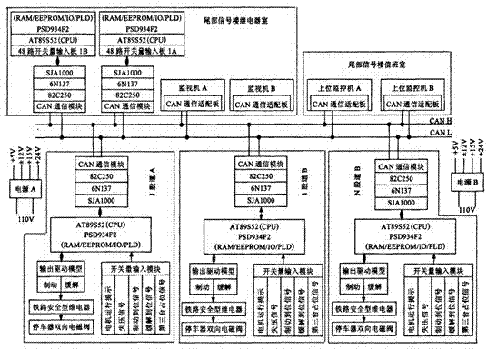
[0021] Such as figure 1 , The new hydraulic controllable parking device control system consists of 3 parts: the relay room of the tail signal building, the duty room of the tail signal building and the field control equipment. They all work in a dual-machine redundant mode and carry out long-distance communication through CAN bus.

[0022] The relay room of the tail signal building includes a monitoring machine and a 48-way switching value acquisition board. The monitoring machine is only used to monitor relevant information such as the status of the on-site parking device, the position of the tail switch, the status of the signal machine, and the idle track; the 48-way switching value acquisition board (ie The lower computer in the relay room) determines the status of the original equipment on the site by collecting the status of the relay-related nodes in the relay ro...


PUM


Abstract

A new type of parker control system based on CAN bus, which consists of three parts: the relay room of the tail signal building, the duty room of the tail signal building and the field control equipment. They all work in a dual-machine redundant mode and perform long-distance communication through CAN bus . This control system overcomes the shortcomings of the existing control system to control the long driving line, saves a lot of cables, reduces construction difficulty and workload, and has the characteristics of strong real-time performance, fast speed, and high reliability, and fully meets the requirements of the parking device at the rear of the marshalling yard. The communication requirements of the online monitoring system are worthy of popularization.

Description

[0001] Technical field [0002] The invention relates to a novel parking device control system based on CAN bus, which is suitable for the mechanical field. Background technique [0003] For a long time, the anti-slip tools at the tail of the hump have mainly used iron shoes as the main shunting equipment. Iron shoes, as a simple speed regulation and anti-slip equipment, were indeed suitable for my country's national conditions and road conditions at the time of the development of the hump. During the anti-skidding operation using iron shoes at the tail of the hump, the operation status of the shunting locomotive was observed through manual contact, and the manual guarantee of "putting shoes" and "removing shoes" was not only labor-intensive and the working environment was harsh, but also The low labor efficiency directly affects the further improvement of the hump tail marshalling ability. What's more serious is that shunting accidents caused by "missing release" and "missin...

Claims


Application Information

Patent Timeline
Patent Type & Authority Applications(China)
IPC IPC(8): G05B19/042
CPCG05B19/0423G05B2219/24215
Inventor 韩会义
Owner 韩会义
Why Eureka
Try Eureka