Wiring terminal box for high-voltage switch station
A terminal block and high-voltage switch technology, applied in the direction of cable joints, etc., can solve the problems of inconvenient maintenance and installation personnel, poor insulation, inconvenient, etc., and achieve the effect of easy cleaning and maintenance, avoiding safety, and convenient cleaning of space
- Summary
- Abstract
- Description
- Claims
- Application Information
AI Technical Summary
Problems solved by technology
Method used
Image
Examples
specific Embodiment 1
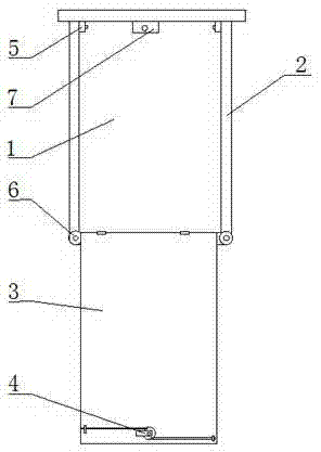
[0024] Such as figure 1 As shown, the terminal box for the high-voltage switch station of the present invention includes a box body with a front side opening and a box door 3 that is located at the front side opening of the box body; the box door 3 of the box body and the box body The lower part is hinged, and the box door 3 is turned down to open the front side opening of the box body. The box body includes a bottom wall 1, a top wall 5, a left side wall, a right side wall 2, and a rear side wall; the bottom wall 1 and the top wall 5 are respectively fixedly connected to the rear side wall. The lower end of the left side wall and the lower end of the right side wall 2 are respectively hinged with the bottom wall 1 . The lower end of the left side wall and the lower end of the right side wall 2 are respectively hinged with the bottom wall through a rotating shaft. The upper end of the left side wall and the upper end of the right side wall 2 are snap-connected with the botto...
specific Embodiment 2
[0026] The terminal box for a high-voltage switch station of the present invention includes a box body with a front opening and a box door 3 that is located at the front opening of the box body; the box door 3 of the box body is hinged to the lower part of the box body, The box door 3 is turned down to open the front side opening of the box body. The box body includes a bottom wall 1, a top wall 5, a left side wall, and a right side wall 2. The left side wall and the right side wall 2 have a symmetrical L-shaped structure, and one end of the left side wall and the right side wall 2 is movably connected by a vertical shaft. , the upper and lower ends of the vertical axis are respectively connected to the top wall 5 and the bottom wall 1 . Chamber door 3 is provided with locking device 4, and this locking device 4 comprises lock core, lock bar, lock plate, and lock core can drive lock bar and lock plate, and left side wall and right side wall 2 are provided with and lock bar. A...
PUM
 Abstract
Description
Claims
Application Information
 - R&D
- Intellectual Property
- Life Sciences
- Materials
- Tech Scout
- Unparalleled Data Quality
- Higher Quality Content
- 60% Fewer Hallucinations
Browse by: Latest US Patents, China's latest patents, Technical Efficacy Thesaurus, Application Domain, Technology Topic, Popular Technical Reports.
© 2025 PatSnap. All rights reserved.Legal|Privacy policy|Modern Slavery Act Transparency Statement|Sitemap|About US| Contact US: help@patsnap.com

