Pre-charging device and method of high-voltage frequency converter

A high-voltage inverter and pre-charging technology, which is applied in the direction of circuit devices, battery circuit devices, output power conversion devices, etc., can solve the problems of high cost, insufficient pre-charging, resistance heating, etc., and achieve low cost and no energy loss , low-cost effect

Inactive Publication Date: 2017-06-20
MCC HUATIAN NANJING AUTOMATION ENG
View PDF6 Cites 10 Cited by
  • Summary
  • Abstract
  • Description
  • Claims
  • Application Information

AI Technical Summary

Problems solved by technology

Although this method can realize the charging of the frequency converter with a low-voltage power supply, there are still some problems, mainly because the rated capacity of the rectifier transformer is much larger than the rated capacity of its auxiliary winding, so when the auxiliary winding is excited, the steady-state excitation The current is very large. Excessive excitation current will cause an excessive voltage drop on the current limiting resistor. If fewer contactors are selected, the resistance value of each bypass is large, and each bypass is suddenly added to the auxiliary current. The voltage on the winding is relatively high, so every time a contactor is used to bypass the resistance, a large impact current will be generated on the low-voltage power supply, and it will also have a certain impact on the DC capacitor in the power unit. If more contactors are selected, Then the cost is higher; secondly, if in order to save costs, the last stage contactor is omitted, and the current limiting resistor used is not bypassed before disconnecting the charging circuit, then the pre-charging is not sufficient considering the voltage drop on the resistor , there will still be an inrush current when the high voltage is powered on; finally, due to the excessive excitation current, the resistor will be seriously heated, so this circuit needs to use a high-power resistor, which is large in size, high in cost and low in efficiency.

Method used


Image

  • Pre-charging device and method of high-voltage frequency converter
  • Pre-charging device and method of high-voltage frequency converter
  • Pre-charging device and method of high-voltage frequency converter

Examples


Embodiment 2

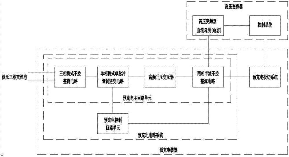
[0033] With reference to Embodiment 1, the pre-charging main circuit unit includes a three-phase bridge type uncontrolled rectification circuit, a unidirectional bridge type single pulse modulation inverter circuit, a high-frequency step-up transformer and a two-phase half-wave uncontrolled rectification circuit;

[0034] The three-phase bridge-type uncontrolled rectification circuit is used to receive the AC voltage output by the low-voltage AC power supply, rectify the received AC voltage to obtain a DC voltage, and output the DC voltage to the unidirectional bridge-type single-pulse modulation inverter circuit;

[0035] The unidirectional bridge-type single-pulse modulation inverter circuit is used to receive a DC voltage, modulate and invert the DC voltage to obtain an AC square wave voltage, and then output the AC square wave voltage to a high-frequency step-up transformer;

[0036] The high-frequency step-up transformer is used to receive the AC square wave voltage, and ste...

Embodiment 3

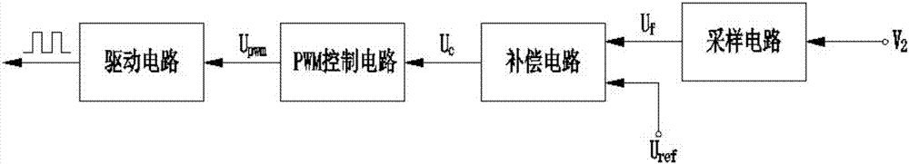
[0040] In combination with Embodiment 1 and Embodiment 2, the pre-charging control loop unit includes a sampling circuit, a compensation circuit, a PWM control circuit, and a driving circuit connected in sequence; the pre-charging control loop unit and the single-phase bridge single pulse modulation The inverter is controlled and connected, and is used to control the turn-on or turn-off of the switching device in the single-phase bridge type single-pulse modulation inverter. Such as image 3 As shown, the pre-charging control loop unit controls the AC square wave output by the single-phase bridge-type single-pulse modulation inverter, so that the AC square wave passes through the high-frequency step-up transformer and the two-phase half-wave does not The amplitude of the DC voltage obtained by controlling the rectifier can be increased from low, and the DC voltage is detected for closed-loop control.

Embodiment 4

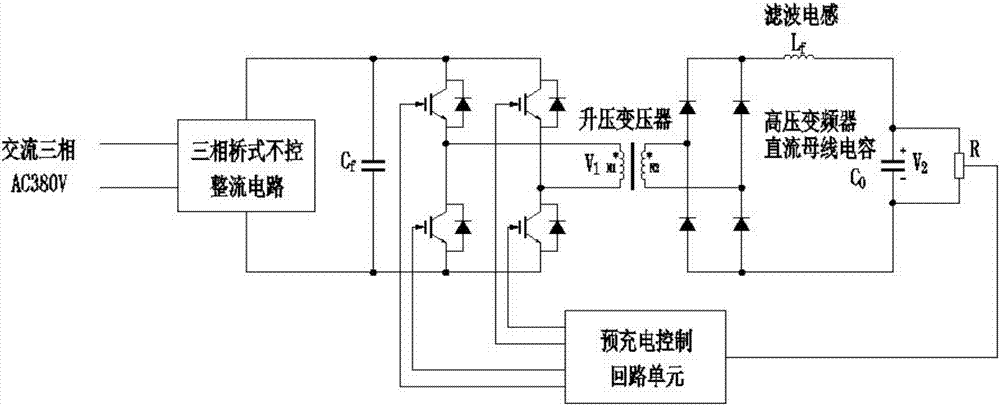
[0042] As a preferred solution of the second embodiment, an inductor for filtering is connected in series between the output end of the two-phase half-wave uncontrolled rectification circuit and the DC bus capacitor of the high-voltage inverter.

[0043] The high-voltage inverter pre-charging device provided by the present invention first passes the input low-voltage AC power through a three-phase bridge-type uncontrolled rectifier circuit, a single-phase bridge-type single-pulse modulation inverter circuit, a high-frequency step-up transformer, and a two-phase half-wave uncontrolled rectifier circuit, that is, after AC / DC-DC / AC-AC / DC conversion, the final output DC voltage charges the DC bus capacitor of the inverter; secondly, by controlling the four switching devices in the single-phase bridge single-pulse modulation inverter circuit The turn-on, turn-off and turn-on time of the time, so that the DC voltage amplitude increases from low to low with a certain slope. The slope ...


PUM


Abstract

The invention discloses a high-voltage inverter pre-charging device and method, including a pre-charging circuit system and a pre-charging switching system; the pre-charging circuit system includes a pre-charging main circuit unit and a pre-charging control circuit unit; the pre-charging main The input end of the loop unit is connected to the low-voltage AC power supply, and the output end of the pre-charging main loop unit is connected to the DC bus capacitor of the high-voltage inverter; the pre-charging control loop unit is used to detect the final output DC voltage of the pre-charging main loop unit , according to the detected DC voltage to control the output voltage of the inverter in the pre-charging main circuit unit; the pre-charging switching system is used to detect the voltage at both ends of the DC bus capacitor of the high-voltage inverter, and send the detection signal to the inverter Control system: The frequency converter control system controls the pre-charging circuit system to cut out, controls the high-voltage switch of the frequency converter to close, or controls the pre-charging circuit system to cut in, and controls the high-voltage switch of the frequency converter to open according to the received signal.

Description

technical field [0001] The invention relates to the technical field of high-voltage frequency converters, in particular to a pre-charging device and method for high-voltage frequency converters Background technique [0002] With the development of power electronics technology, as a product of the development of power electronics technology, frequency converters have been widely used in various fields of the national economy, such as metallurgy, petrochemical, municipal, electric power and other industries, and are playing an increasingly important role. Yes, the application of high-voltage and high-power inverters is becoming more and more extensive. Among the high-voltage inverters, the high-voltage and high-power inverters composed of power modules connected in series are favored by many inverter manufacturers, scientific research institutes, engineering and technical personnel, and users as inverters that are suitable for China's national conditions and have excellent per...

Claims


Application Information

Patent Timeline
Patent Type & Authority Applications(China)
IPC IPC(8): H02M7/219H02M3/335H02J7/34
CPCH02M7/219H02J7/345H02M3/33569
Inventor 司伟
Owner MCC HUATIAN NANJING AUTOMATION ENG
Why Eureka
Try Eureka