Loudspeaker sound generation hole plugging processing method and device and terminal equipment

A processing method and terminal equipment technology, applied to speaker screens, chemical instruments and methods, frequency/direction characteristic devices, etc., can solve the problems of speaker sound hole area reduction, deposition, sound mixed with noise, etc., to improve user experience, The effect of reducing processing difficulty

Inactive Publication Date: 2017-06-20
GUANGDONG OPPO MOBILE TELECOMM CORP LTD
View PDF7 Cites 27 Cited by
  • Summary
  • Abstract
  • Description
  • Claims
  • Application Information

AI Technical Summary

Problems solved by technology

[0004] However, the dust-proof mesh prevents dust, liquid, etc. from entering the interior of the speaker unit, and it is also easy to deposit dust, liquid, etc. on the mesh
With the continuous accumulation of dust, liquid, etc. on the dust-proof mesh, the area of ​​the sound hole of the speaker will decrease, which will result in a decrease in the volume of the sound output by the speaker or noise in the output sound

Method used


Image

  • Loudspeaker sound generation hole plugging processing method and device and terminal equipment
  • Loudspeaker sound generation hole plugging processing method and device and terminal equipment
  • Loudspeaker sound generation hole plugging processing method and device and terminal equipment

Examples


example 1

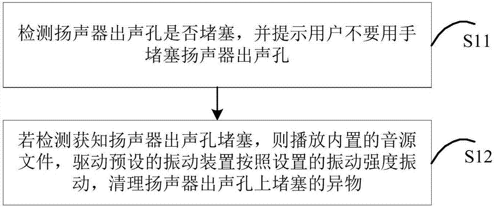
[0047] Example 1: The vibration intensity of the driven vibration device is constant when the built-in audio file is played.

[0048] In this example, the vibration intensity of the vibration device driven when the built-in audio file is played is set to be constant, then when the vibration device is driven by playing the audio file, the vibration intensity of the vibration device will not change during the playback of the audio file. For example, assume that the vibration intensity of the vibration device driven by the built-in sound source file is set to 0.45mm / s when playing. When it is detected that the sound outlet of the speaker of the terminal device is blocked, the vibration device is driven by playing the built-in audio file, and the vibration intensity of the vibration device is always 0.45mm / s during the playback of the audio file.

example 2

[0049] Example 2: When the built-in audio file is played, the vibration intensity of the driven vibration device increases according to the playing time.

[0050] In this example, the vibration intensity of the vibration device driven by the built-in audio file is set to increase according to the playing time. Increments as the playback time progresses.

[0051] For example, assuming that the playback time of the built-in audio file is 60s, set the vibration intensity of the vibration device driven 20s before playback to 0.45mm / s, and set the vibration intensity of the vibration device driven from 21s to 40s to 0.71mm / s s, set the vibration intensity of the vibration device driven during 41s to 60s of playback as the maximum vibration intensity value of the vibration device 1mm / s. When it is detected that the sound hole of the speaker of the terminal device is blocked, by playing the built-in audio file, the preset vibration device is driven to vibrate according to the increa...


PUM


Abstract

The invention provides a loudspeaker sound generation hole plugging processing method and device and terminal equipment. The method comprises the steps that whether the sound generation hole of a loudspeaker is plugged is detected, and the user is prompted not to plug the sound generation hole of the loudspeaker by the hand; and if the detection result indicates that the sound generation hole of the loudspeaker is plugged, a built-in audio file is played, a preset vibration device is driven to vibrate according to the set vibration intensity so that the plugged foreign matter on the sound generation hole of the loudspeaker can be cleaned. With application of the method, automatic cleaning of dust or foreign material on dust screen cloth can be realized without machine disassembling when the dust screen cloth is plugged by the dust and the liquid so that the processing difficulty can be reduced and the user experience can be enhanced.

Description

technical field [0001] The present invention relates to the technical field of terminal equipment, in particular to a method and device for dealing with blockage of a sound outlet of a loudspeaker, and a terminal equipment. Background technique [0002] The loudspeaker can increase the volume of the output sound, and is almost an essential component of terminal equipment, MP4 and other equipment. In order to ensure the normal output of the speaker's sound from the device, several small holes are usually opened on the device in the direction of the speaker's sound hole, so that it is inevitable that dust, liquid, etc. enter the device through the small holes and cause the speaker's sound hole to be blocked of. [0003] In related technologies, in order to prevent dust, liquid, etc. from entering the speaker unit of the mobile phone and affecting the output of the speaker sound, a layer of dust-proof mesh is usually pasted on the sound channel of the speaker. The aperture of ...

Claims


Application Information

Patent Timeline
Patent Type & Authority Applications(China)
IPC IPC(8): H04R29/00
CPCH04R29/001H04R1/023H04R2499/11H04R1/22B08B7/02G06F3/165
Inventor 孙禄
Owner GUANGDONG OPPO MOBILE TELECOMM CORP LTD
Why Eureka
Try Eureka