Benign positional vertigo therapy apparatus
A therapeutic instrument and a benign technology, applied in the field of medical equipment, can solve problems such as heart burden, breathing effort, and difficult treatment of patients
- Summary
- Abstract
- Description
- Claims
- Application Information
AI Technical Summary
Problems solved by technology
Method used
Image

Examples
Embodiment Construction
[0017] The present invention will be described in further detail below in conjunction with the accompanying drawings and embodiments. Wherein the same components are denoted by the same reference numerals. It should be noted that the words "front", "rear", "left", "right", "upper" and "lower" used in the following description refer to the directions in the drawings, and the words "bottom" and "top "Face", "inner" and "outer" refer to directions toward or away from, respectively, the geometric center of a particular component.
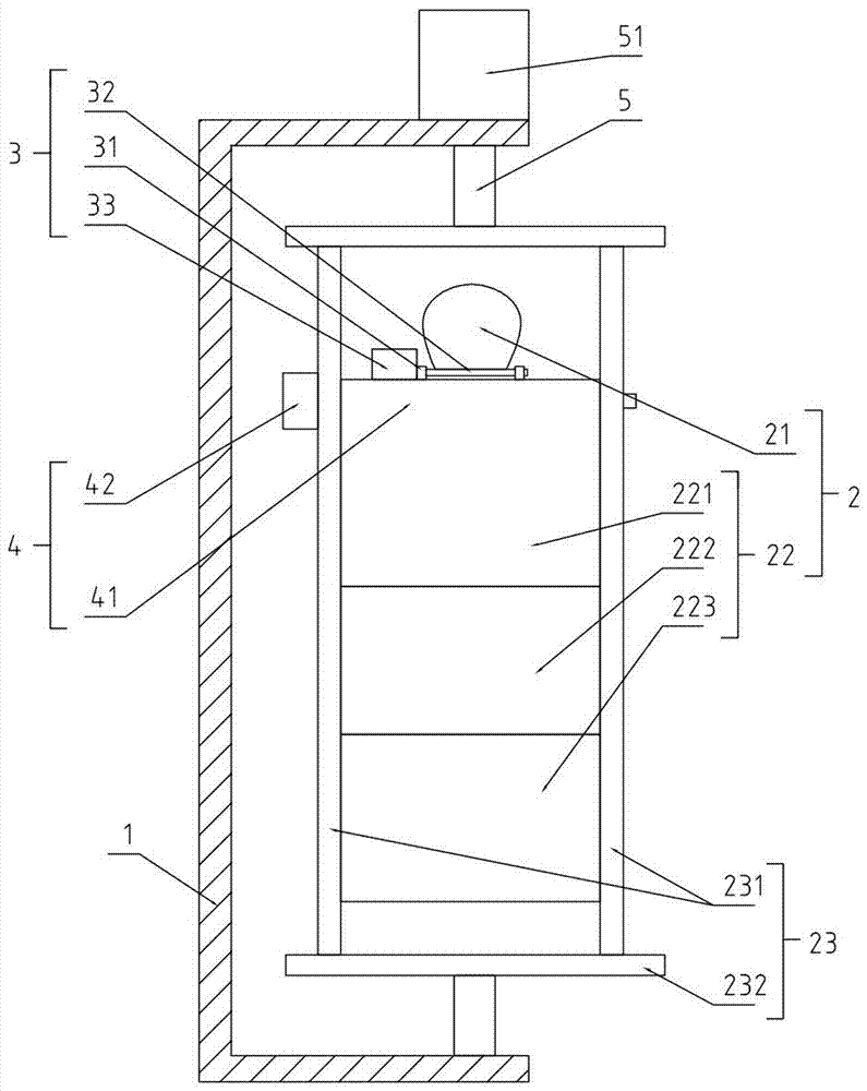
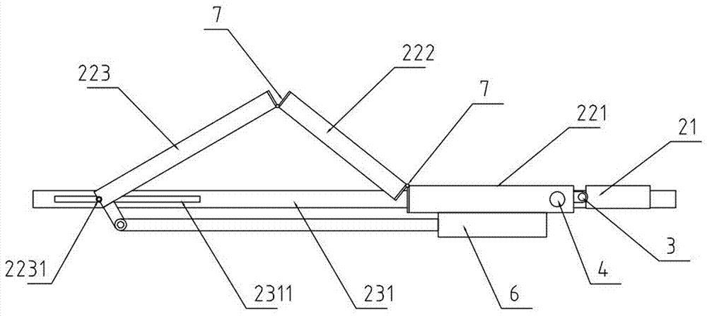
[0018] refer to figure 1 , 2 As shown, a benign positional vertigo treatment instrument includes a frame 1 and a correction position 2 arranged on the frame 1 for carrying the patient. The correction position 2 includes a correction head cushion 21 and a seat cushion 22 and is used for installing Lean on the mounting frame 23 of the seat cushion 22, and one end of the length direction of the lean on seat cushion 22 is provided with a first drive devi...
PUM
 Abstract
Description
Claims
Application Information