
Swirling air system for rotor piston type concrete spraying machine and method

A technology of concrete spraying machine and rotor piston, which is applied in spraying device, liquid spraying device, etc., to achieve the effect of easy installation, easy on-site maintenance and simple structure

Pending Publication Date: 2017-06-23
陕西金石混凝土科技发展有限公司
View PDF8 Cites 0 Cited by
  • Summary
  • Abstract
  • Description
  • Claims
  • Application Information

AI Technical Summary

Problems solved by technology

[0003] The technical problem to be solved by the present invention is to provide a swirling air system and method for a rotor-piston concrete sprayer in view of the deficiencies in the above-mentioned prior art. The nozzle sprays to the sprayed surface, which not only realizes the smoothness of sprayed concrete, but also avoids the problems of blocked pipes, adhesion and discharge pulse dripping of sprayed concrete

Method used


Image

  • Swirling air system for rotor piston type concrete spraying machine and method
  • Swirling air system for rotor piston type concrete spraying machine and method
  • Swirling air system for rotor piston type concrete spraying machine and method

Examples


Embodiment 1

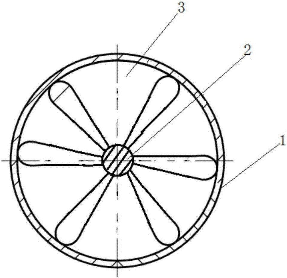
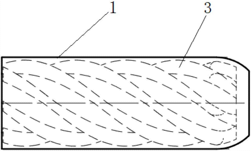
[0035] The swirl device of this system can also set the wind shaft 2 as hollow, and open an air inlet on the side wall of the swirl device to connect to the wind station, connect one end of the swirl device with the feeding pipe of the pump, and the other One end is connected to the nozzle, and the feeding pipe sends the mixed material into the inside of the wind shaft 2. After the compressed air provided by the wind station enters from the side wall of the swirl device, it passes through the spiral air induction channel on the outer wall of the wind shaft 2 and becomes a swirling wind. The front end of the swirling device mixes the swirling wind and the mixture and then sprays it out through the nozzle. It can meet the needs of the pumping concrete injection machine, reduces the quality requirements of the pumping machine for the mixture, and avoids the occurrence of pump blockage.

Embodiment 2

[0037] The swirl device also includes rifling on the inner wall of the casing 1, and the rifling is arranged spirally along the inner wall of the casing 1 for converging the swirling wind into one point and then spraying it out, which can increase the wind force of the swirling wind.

[0038] Preferably, the air outlet end of the casing 1 is provided with a closing structure, and the inner diameter of the air outlet end is smaller than the air inlet end of the casing 1, so as to further improve the spiral wind power.

[0039] see figure 1 As shown, the present invention discloses a method for the swirling wind system of the rotor piston concrete sprayer, comprising the following steps:

[0040] S1. Install a swirl device at the air inlet of the rotor piston jet machine, and then connect the swirl device with the air supply pipe of the wind station;

[0041] S2, adding cement, sand, pea stone, admixture and water into the mixer to make fluid concrete;

[0042] S3, start the w...


PUM


Abstract

The invention discloses a swirling air system for a rotor piston type concrete spraying machine and a method. The system comprises an air station, a swirling device and the rotor piston type concrete spraying machine; the air station is connected with the rotor piston type concrete spraying machine through an air supply pipeline; and the swirling device is arranged between the air supply pipeline and the rotor piston type concrete spraying machine, is located at the air inlet of the rotor piston type concrete spraying machine and is used for swirling compressed air produced by the air station to provide rotating air power for the rotor piston type concrete spraying machine. With the system, a concrete mix is delivered to a spray pipe by the aid of high-speed swirling air until the concrete mix is sprayed by a spray head to a sprayed surface, the concrete spraying smoothness is realized, and the problems of pipeline blockage caused by the sprayed concrete, adhesion and discharging pulse dripping can also be avoided.

Description

technical field [0001] The invention belongs to the technical field of concrete spraying construction, and in particular relates to a swirling air system and method for a rotor-piston concrete spraying machine. Background technique [0002] No matter the existing concrete spraying construction uses a large trolley or a small spraying machine, there are many problems such as concrete spraying pipe plugging and discharge pulse dripping, which seriously affect the sprayed concrete construction and quality. However, the existing sprayed concrete equipment only feeds the material directly on the pipeline through the direct current wind. Although the mixing is relatively uniform, the sprayed concrete will be dispersed in the pipeline due to the attenuation of the wind pressure and the difference in the specific gravity of the mixture in the pipeline. The quick-setting adhesion that reacts with the quick-setting agent makes pipe plugging and pulse dripping occur frequently with the...

Claims


Application Information

Patent Timeline
IPC IPC(8): B05B7/24
CPCB05B7/2491
Inventor 王宏军李军强
Owner 陕西金石混凝土科技发展有限公司
Learn More