
Frame corner connecting piece glue dispenser capable of feeding automatically and application method thereof

A corner connector and automatic feeding technology, which is applied to devices and coatings that apply liquid to the surface, can solve the problems of continuous production and low production efficiency, and achieve improved production efficiency, accurate dispensing, and high economy. effect of benefit

Inactive Publication Date: 2017-06-23
石狮市鑫跃精密科技有限公司
View PDF9 Cites 10 Cited by
  • Summary
  • Abstract
  • Description
  • Claims
  • Application Information

AI Technical Summary

Problems solved by technology

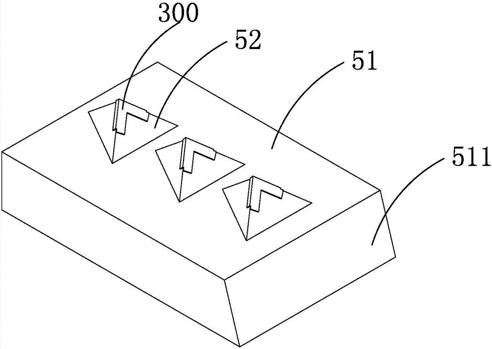
The existing method of applying glue to the corner connectors is as follows: the corner connectors are placed on the placement frame, and glue is dispensed by a glue dispenser. The placement frame is provided with a number of sharp corners that fit the shape of the corner connectors, so that Fixed, in the existing equipment, there are two ways to grab the corner connectors after each dispensing, one is to disassemble the placement frame as a whole, and the other is to directly clamp the corner connectors, neither of which can be used for continuous production. Low production efficiency

Method used


Image

  • Frame corner connecting piece glue dispenser capable of feeding automatically and application method thereof
  • Frame corner connecting piece glue dispenser capable of feeding automatically and application method thereof
  • Frame corner connecting piece glue dispenser capable of feeding automatically and application method thereof

Examples


Embodiment Construction

[0021] The present invention will be further described below through specific embodiments.

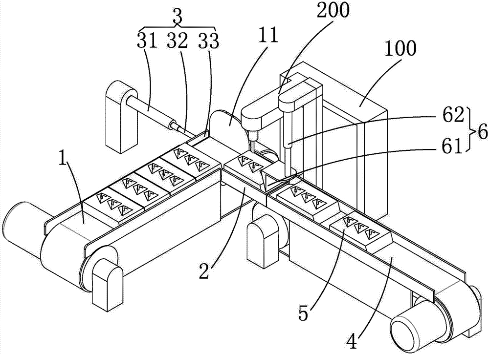
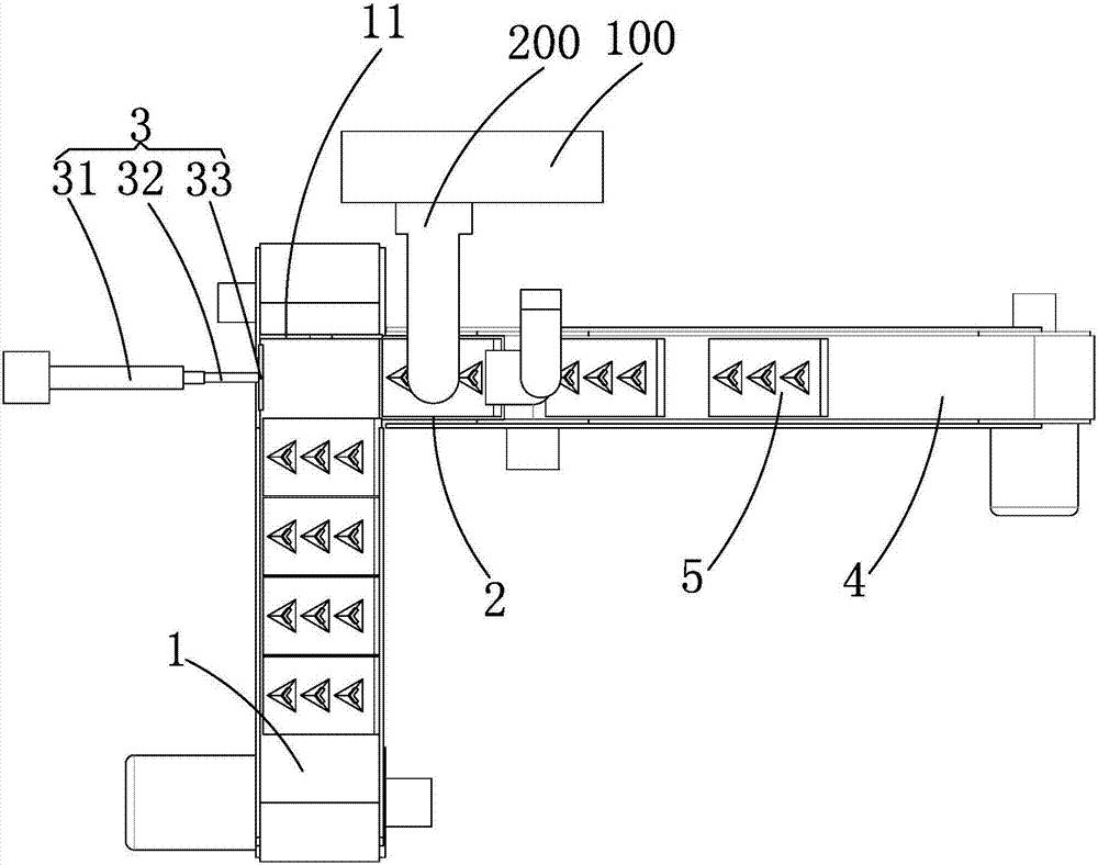
[0022] Such as figure 1 with figure 2 As shown, an automatic feeding frame corner connector dispensing machine according to the present invention includes a frame 100, a dispensing device 200 arranged on the frame 100 and a feeding device arranged below the dispensing device 200 .

[0023] The dispensing device 200 is the same as the common type of dispensing machine on the market. Compressed air is sent into the glue bottle (syringe), and the glue is pressed into the feeding pipe connected to the piston chamber. When the piston is in the upstroke, the piston chamber is filled. Glue, when the piston pushes down the dispensing needle, the glue is pressed out from the nozzle, and the dispenser moves in three axes.

[0024] Such as figure 1 with figure 2 As shown, the feeding device includes a feeding conveyor belt 1, a dispensing table 2, a push mechanism 3, a feeding conveyor bel...


PUM


Abstract

The invention relates to the field of television frame machining equipment, in particular to a frame corner connecting piece glue dispenser capable of feeding automatically. The frame corner connecting piece glue dispenser comprises a machine frame and a glue dispensing device arranged on the machine frame, and is characterized in that the glue dispenser further comprises a feeding device arranged below the glue dispensing device; the feeding device comprises a feeding conveying belt, a glue dispensing platform, a pushing mechanism, a discharging conveying belt and a plurality of storing frames; the conveying direction of the feeding conveying belt is perpendicular to that of the discharging conveying belt; the glue dispensing platform is arranged between the feeding conveying belt and the discharging conveying belt; the pushing device comprises a pushing air cylinder and a pushing rod, and the pushing air cylinder pushes the pushing rod to move back and forth in the direction same as that of the discharging conveying belt; and all the storing frames sequentially move on the feeding conveying belt, the glue dispensing platform and the discharging conveying belt. Through the frame corner connecting piece glue dispenser capable of feeding automatically and an application method thereof which are provided by the invention, automatic and continuous feeding can be achieved, the procedures of feeding, glue dispensing and discharging are conducted in a synergistic mode, glue dispensing is accurate, the production efficiency is greatly improved, and the high economic benefit is achieved.

Description

technical field [0001] The invention relates to the field of TV frame processing equipment, in particular to a frame corner connector dispenser for automatic feeding and a use method thereof. Background technique [0002] The frame of the TV or monitor is usually made of aluminum alloy frame, which has the advantages of light weight and beautiful appearance. After the aluminum alloy is processed into a strip-shaped LCD screen frame, it needs to be spliced ​​into a rectangular frame. The connection method of the aluminum alloy strip frame usually has connectors Adhesive, welding or locking connections are widely used because adhesive bonding can save space, make the structure more compact, and do not need to process locking holes and reduce processing procedures. Existing corner connectors are placed at the corner joints of two strip frames after being coated with glue. In order to closely connect the corner connectors with the bar frames, it is usually necessary to use a pre...

Claims


Application Information

Patent Timeline
Patent Type & Authority Applications(China)
IPC IPC(8): B05C5/02B05C13/02
CPCB05C5/0212B05C13/02
Inventor 许佳福
Owner 石狮市鑫跃精密科技有限公司
Learn More