End head cutting device for blank part of gear shaft

A cutting device and technology of blank parts, applied in metal processing and other directions, can solve the problems of uneven cutting of gear shafts and affect the processing of gear shafts, etc., achieve efficient and accurate cutting, improve cutting yield, and promote the effect of good application value

Inactive Publication Date: 2017-06-23
HUBEI XINYEGANG STEEL AUTO PARTS
View PDF0 Cites 7 Cited by
  • Summary
  • Abstract
  • Description
  • Claims
  • Application Information

AI Technical Summary

Problems solved by technology

[0002] In the gear shaft processing workshop, the casted gear shaft blanks are usually two gear shafts connected together, and there are often redundant margins at both ends, which do not meet the requirements. In this case, they must be cut. After that, the next step of processing can be carried out. In general cutting, the gear shaft is sent to the bottom of the ordinary cutting machine through the conveying device for direct cutting. If there is no specific fixing device, the gear shaft will move left and right when the cutting device is cutting, resulting in cutting on both sides of the gear shaft. Unevenness, which in turn affects the next step of processing the gear shaft

Method used


Image

  • End head cutting device for blank part of gear shaft
  • End head cutting device for blank part of gear shaft

Examples


Embodiment Construction

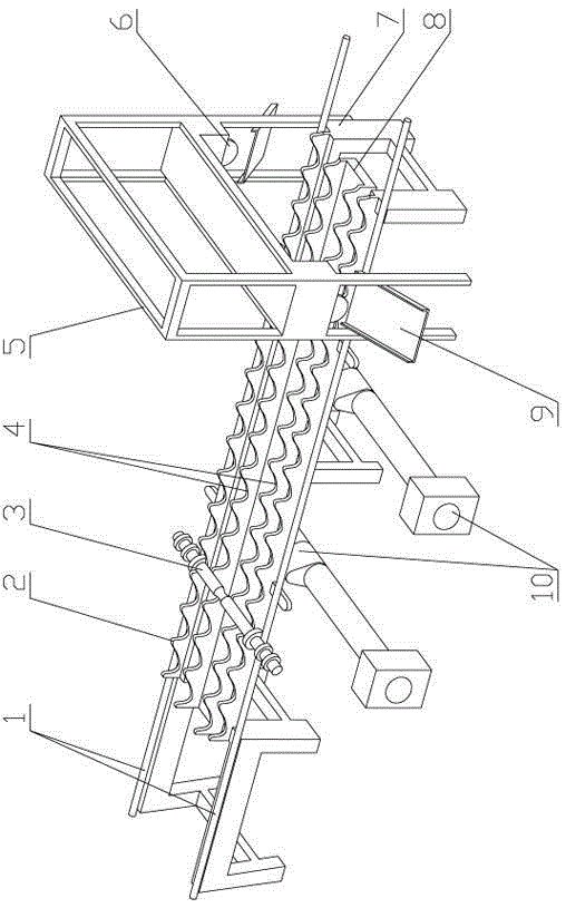
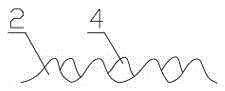
[0012] see figure 1 , figure 2 , the present invention is a cutting device for the end of a gear shaft blank, which has a base bracket 7, two rows of fixed conveying teeth 2 are symmetrically arranged on the front and rear sides of the base bracket, and a movable plate 8 is arranged between the two rows of fixed conveying teeth , two rows of movable conveying teeth 4 are arranged symmetrically on both sides of the movable plate, and the tooth tops of the movable conveying teeth and the tooth tops of the fixed conveying teeth are alternately arranged. The bottom of the movable plate is provided with a cam transmission mechanism 10. The teeth move up and down intermittently under the drive of the cam transmission mechanism; a positioning round steel 1 is provided on the outside of both sides of the fixed conveying teeth, and a cutting bracket 5 is arranged across the two sides of the positioning round steel. A set of cutting machine 6 is respectively provided on the front and ...


PUM


Abstract

The invention is a cutting device for the end of a gear shaft blank, which has a base bracket, two rows of fixed conveying teeth are symmetrically arranged on the front and rear sides of the base bracket, and a movable plate is arranged between the two rows of fixed conveying teeth. There are two rows of movable conveying teeth symmetrically arranged on both sides. The tooth tops of the movable conveying teeth and the tops of the fixed conveying teeth are arranged alternately. The bottom of the movable plate is equipped with a cam transmission mechanism. The movable plate and the movable conveying teeth are driven by the cam transmission mechanism. Make intermittent up and down movements; there is a positioning round steel on both sides of the fixed conveying teeth, a cutting bracket is installed across the two sides of the positioning round steel, and a cutting machine is installed on the front and rear sides of the cutting bracket. , the cutting machine is used to cut the remaining material at both ends of the gear shaft blank conveyed by the movable conveying teeth; the invention has the advantages of simple and compact structure, accurate limit, efficient and precise cutting, and has good promotion and application value, mainly used in The gear shaft blank is being processed.

Description

technical field [0001] The invention relates to the technical field of gear shaft processing equipment, in particular to a gear shaft blank end cutting device. Background technique [0002] In the gear shaft processing workshop, the casted gear shaft blanks are usually two gear shafts connected together, and there are often redundant margins at both ends, which do not meet the requirements. In this case, they must be cut. After that, the next step of processing can be carried out. In general cutting, the gear shaft is sent to the bottom of the ordinary cutting machine through the conveying device for direct cutting. If there is no specific fixing device, the gear shaft will move left and right when the cutting device is cutting, resulting in cutting on both sides of the gear shaft. Unevenness, which in turn affects the next step of processing the gear shaft. Contents of the invention [0003] The purpose of the present invention is to solve the above-mentioned problems ex...

Claims


Application Information

Patent Timeline
IPC IPC(8): B23D79/00B23Q7/00
CPCB23D79/00B23Q7/00
Inventor 余三中曹四喜
Owner HUBEI XINYEGANG STEEL AUTO PARTS
Why Eureka
Try Eureka