Brittle substrate and laser cutting method therefor

A brittle substrate, laser cutting technology, applied in the field of brittle substrates, laser cutting non-metallic or brittle substrates, can solve the problems of affecting cutting accuracy, difference in growth distance, poor cutting yield of glass substrates, etc., and achieve high cutting yield Effect

Active Publication Date: 2009-09-16
FOXSEMICON INTEGRATED TECHNOLOGY (SHANGHAI) INC +1
View PDF0 Cites 7 Cited by
  • Summary
  • Abstract
  • Description
  • Claims
  • Application Information

AI Technical Summary

Problems solved by technology

from figure 2 It can be seen from the figure that when the initial cracks and laser cutting are performed sequentially along a single direction (that is, the first direction A1), the initial cracks at the starting ends of the cutting lines A10, A11, A12, and A13 in the first direction are completely broken and have The growth distance difference along the A1 direction (eg figure 2 The solid line part of the first direction cutting line A10, A11, A12, A13), so that the second direction cutting line A20 adjacent to the starting end of the first direction cutting line A10, A11, A12, A13 cannot cross the first direction cutting line (e.g. A10) full break leads to cutting failure (e.g. figure 2 The part indicated by the middle arrow F1), or the crack growth along other directions deviated from the A2 direction (such as figure 2 The part indicated by the middle arrow F2) affects the cutting accuracy; which in turn leads to poor cutting yield of the glass substrate

Method used


Image

  • Brittle substrate and laser cutting method therefor
  • Brittle substrate and laser cutting method therefor
  • Brittle substrate and laser cutting method therefor

Examples


Embodiment Construction

[0019] The embodiments of the present invention will be further described in detail below in conjunction with the accompanying drawings.

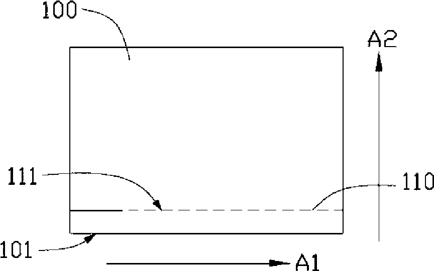
[0020] see Figure 3 to Figure 5 , the method for laser cutting a brittle substrate provided by an embodiment of the present invention includes the following steps.

[0021] Such as image 3 As shown, a brittle substrate 100 is provided, and a first cutting line 110 is formed on the brittle substrate 100 adjacent to an edge 101 of the brittle substrate 100 by a laser cutting process, and the first cutting line 110 extends along the direction A1. Wherein, the brittle substrate 100 is usually a non-metallic substrate such as a ceramic substrate, a glass substrate, a quartz substrate, a glass silicon wafer, or a light emitting diode wafer. The brittle substrate 100 can be a square plate (such as image 3 shown), or other shapes according to actual needs, such as round pieces. The laser cutting process generally includes the steps of: (a) u...


PUM


Abstract

The invention relates to a laser cutting method for a brittle substrate, which comprises the following steps that: a brittle substrate is provided; a first cutting line extending along a first direction at the position adjacent to one edge of the brittle substrate is formed by a laser cutting process; an initiate crack starting from the edge and crossing the first cutting line at the position adjacent to the starting end of the first cutting line on the brittle substrate is formed, and the initial crack extends along a second direction different from the first direction; and a second cutting line extending along the second direction is formed along the initial crack on the brittle substrate by the laser cutting process. The invention also provides a brittle substrate manufactured by the method.

Description

technical field [0001] The invention relates to cutting and separation technology, especially a method for laser cutting non-metallic or brittle substrates and the brittle substrates produced by the method. Background technique [0002] see figure 1 , the method of laser cutting brittle substrates generally uses a laser that matches the strong absorption characteristics of the brittle substrate, such as a carbon dioxide (CO2) laser beam 20 to heat the surface of the glass substrate 10, and then partially cools it with a cooling fluid 30, and then on the surface of the glass substrate 10 Due to the thermal stress generated by the sharply changing temperature difference, the edge of the glass substrate 10 with initial cracks (initial crack) 11 is cracked, and the direction of movement of the laser beam 20 (such as figure 1 (indicated by the middle arrow) grows into blind cracks (blind cracks) 14 , and then can form cutting lines extending along a predetermined direction on th...

Claims


Application Information

Patent Timeline
Patent Type & Authority Applications(China)
IPC IPC(8): B23K26/38C03B33/09
Inventor 周祥瑞何仁钦黄俊凯傅承祖
Owner FOXSEMICON INTEGRATED TECHNOLOGY (SHANGHAI) INC
Why Eureka
Try Eureka