an electroplating device

An electroplating device and electroplating solution technology, which is applied in the direction of current insulation device, contact device, plating tank, etc., can solve the problems of deformation of insulating base plate, uneven electroplating layer, and damage of small parts, so as to avoid loose connection and good plating effect , the effect of improving safety

Inactive Publication Date: 2019-02-05
湖南省鎏源新能源有限责任公司
View PDF7 Cites 0 Cited by
  • Summary
  • Abstract
  • Description
  • Claims
  • Application Information

AI Technical Summary

Problems solved by technology

When the electroplating solution is about to be drained, there is no lubrication of the electroplating solution between the small parts and the electrode ring, and dry friction is formed between the small parts and the electrode ring, coupled with the increase of the line speed, it is easy to cause damage to the small parts
[0005] 2. The increase of defective products in electroplating
The gasket is connected to the insulating bottom plate and the electrode ring through screws. The screw tightening torque is different, so that the gap between the electrode ring and the insulating bottom plate is different. During the rotation, it is easy to cause uneven force on the processing container, resulting in insulation The deformation of the bottom plate, which in turn makes it difficult to control the size of the gap between the insulating bottom plate and the electrode ring; some small parts are easy to get stuck in the gap and cannot be completely electroplated, or the electroplating layer is uneven, which reduces the qualified rate of electroplating

Method used


Image

  • an electroplating device
  • an electroplating device
  • an electroplating device

Examples


Embodiment Construction

[0028] In order to make the technical means, creative features, goals and effects achieved by the present invention easy to understand, the present invention will be further described below in conjunction with specific embodiments.

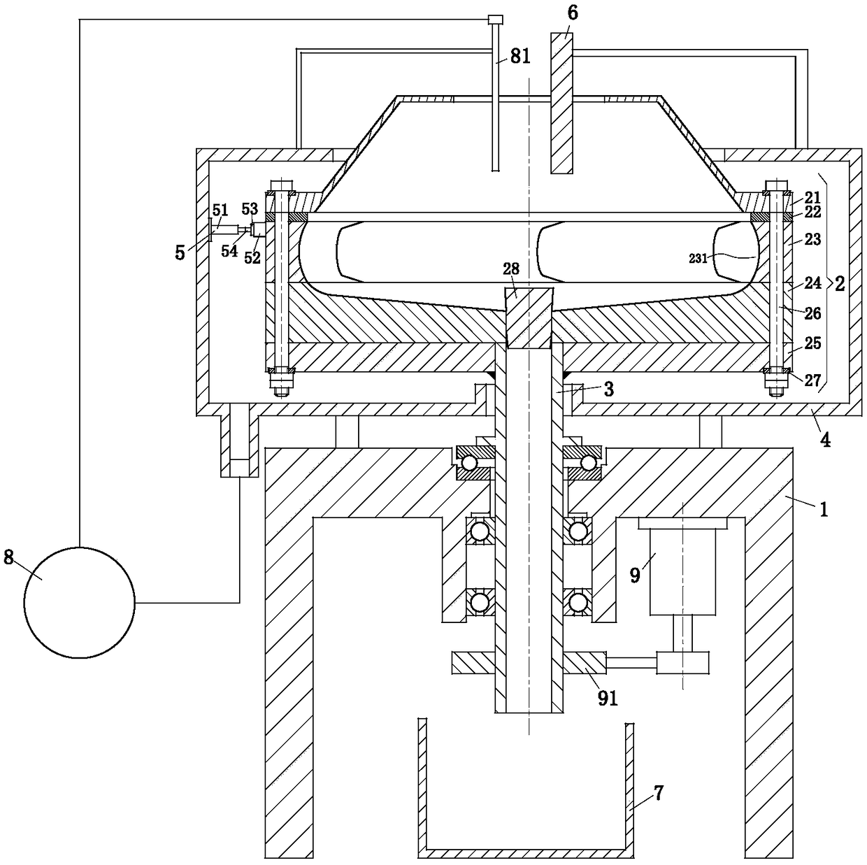
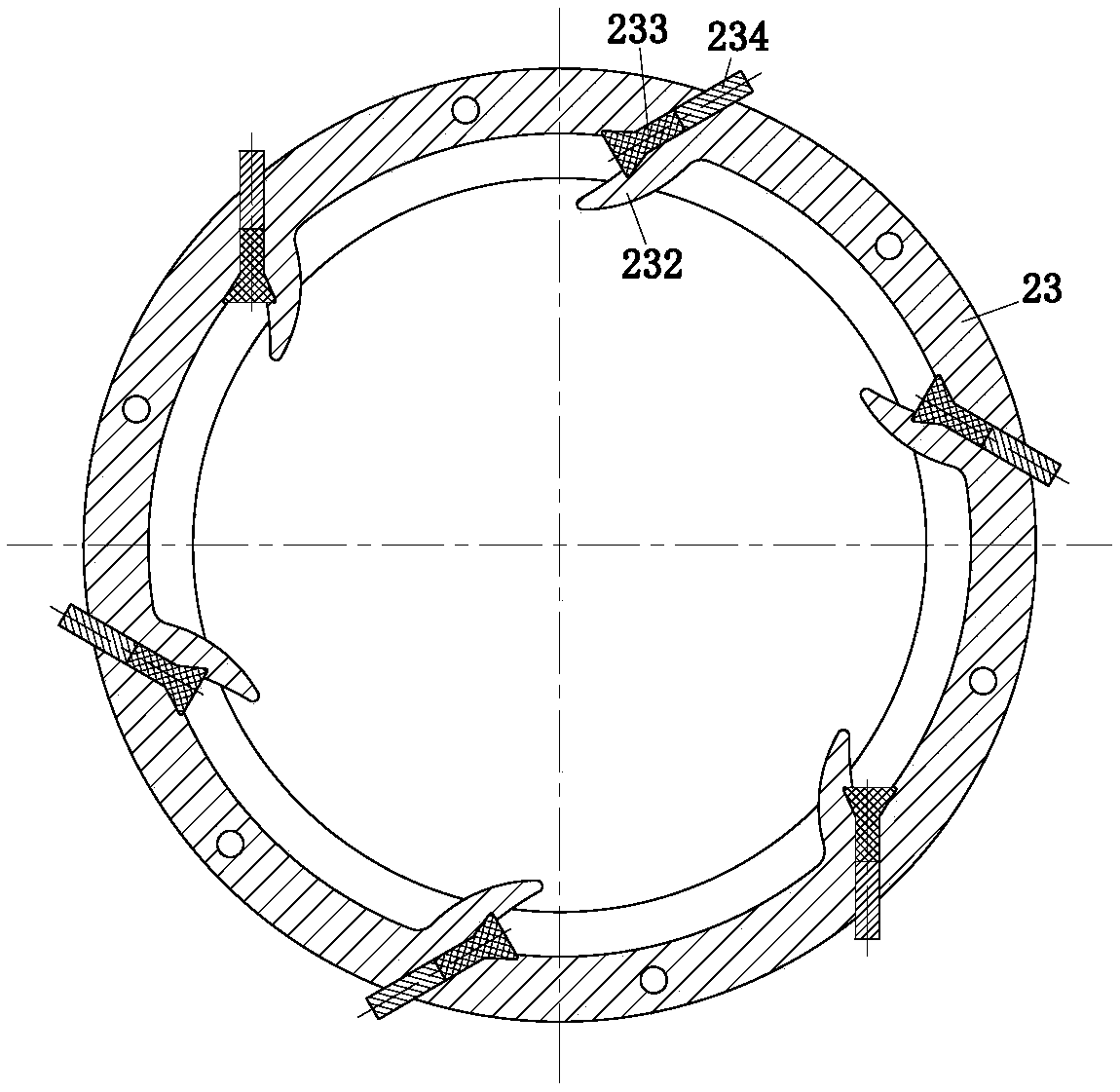
[0029] Such asfigure 1 and figure 2 As shown, an electroplating device according to the present invention includes a support 1, a processing container 2, a hollow shaft 3, a recovery container 4, a brush unit 5, an anode rod 6, a storage tank 7, a circulation pump 8, a motor 9 and The controller, the processing container 2 is located above the support 1 and is connected to the support 1 through a hollow shaft 3; the hollow shaft 3 is installed on the support 1 through a thrust bearing and a deep groove ball bearing, and the processing container 2 The electroplating chamber communicates with the hollow rotating shaft 3, and the plated parts in the electroplating chamber can be discharged through the hollow rotating shaft 3; the recovery container ...


PUM


Abstract

The invention relates to the field of electroplating equipment and particularly relates to an electroplating device. The electroplating device comprises a support seat, a processing container, a hollow rotating shaft, a recycling container, an electric brush unit, an anode bar, a storage box, a circulation pump, a motor and a controller, wherein the processing container is located above the support seat and is connected with the support seat through the hollow rotating shaft; the recycling container is used for recycling electroplating liquid discharged by the processing container; the electric brush unit is used for enabling the processing container to be connected with a cathode of a power supply; the storage box is used for storing electroplated parts discharged out of the hollow rotating shaft; the circulation pump is used for circularly utilizing the electroplating liquid; the motor is used for driving the hollow rotating shaft to rotate. The electroplating device is mainly applied to electroplating of powder with size of 0.1-5000 microns and small parts such as superminiature capacitors, resistors, diodes, connectors, spring switches, nails, bolts, nuts and gaskets and the like; the electroplating quality of the small parts can be improved; the service life of the processing container can be prolonged; the damage rate of the small parts can be reduced; and the safe using performance of the electroplating device can be improved.

Description

technical field [0001] The invention relates to the field of electroplating equipment, in particular to an electroplating device. Background technique [0002] A Chinese patent with publication number 101139732 discloses an electroplating treatment device for small parts. The electroplating device uses a vertical rotating shaft to rotate the processing container containing the small parts so that the small parts contact the electrode ring, and the electroplating solution Small parts are plated by passing electricity from the electrodes to the plating solution in the processing container while flowing from the inside to the outside of the processing container. The processing container has an outflow mechanism for circulating the plating solution from the inside of the processing container to the outside. In this device, as the outflow mechanism, gaskets with a thickness smaller than that of the small parts are evenly distributed on the insulating base plate. The gasket is p...

Claims


Application Information

Patent Timeline
Patent Type & Authority Patents(China)
IPC IPC(8): C25D19/00C25D17/00C25D21/10C25D21/12C25D17/02
CPCC25D17/005C25D17/008C25D17/02C25D21/10C25D21/12
Inventor 林春芳葛晶云陈青青夏巧巧
Owner 湖南省鎏源新能源有限责任公司
Why Eureka
Try Eureka