Eureka AIR delivers breakthrough ideas for toughest innovation challenges, trusted by R&D personnel around the world.

Foundation pit supporting structure and construction method thereof

A foundation pit support and construction method technology, which is applied in the direction of foundation structure engineering, excavation, construction, etc., can solve the problems of high cost of mechanical equipment, low surface layer resistance, and difficult disposal of waste mud, so as to achieve low project cost and increase The effect of improving safety and anti-overturning ability

Inactive Publication Date: 2017-06-23
CHINA 19TH METALLURGICAL CORP +1
View PDF4 Cites 4 Cited by
  • Summary
  • Abstract
  • Description
  • Claims
  • Application Information

AI Technical Summary

Problems solved by technology

[0004] The overall stability of the support structure formed by sheet pile support and row pile support is good, but the cost of mechanical equipment is high and the engineering volume is large
Reinforced concrete underground diaphragm wall is a structural form that is more expensive than manual excavation piles and rotary excavation piles, and it is difficult to dispose of waste mud, which is easy to cause environmental pollution
Compared with the above-mentioned support methods, soil nail anchor support has lower cost, convenient construction, and is green and environmentally friendly. However, the resistance of the surface layer is very small, and the soil nails are arranged closely. , it is a little difficult to construct

Method used


Image

  • Foundation pit supporting structure and construction method thereof
  • Foundation pit supporting structure and construction method thereof

Examples


Embodiment Construction

[0031] The present invention will be further described below in conjunction with the accompanying drawings and embodiments.

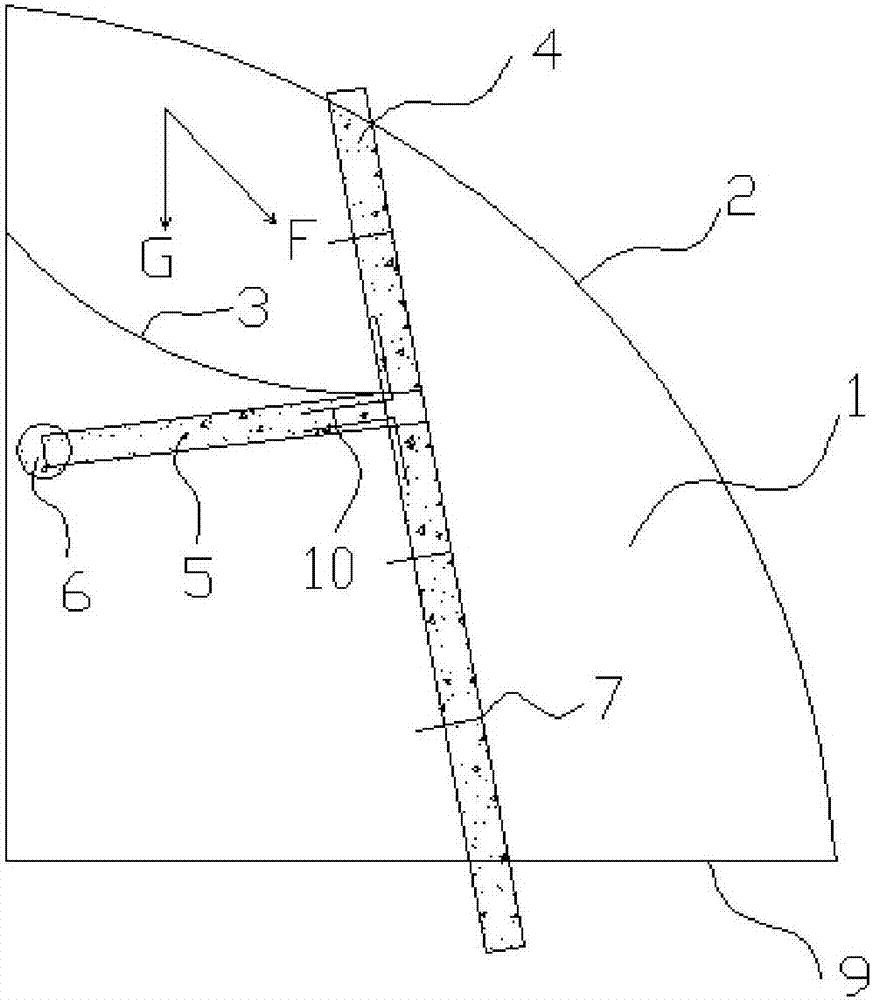
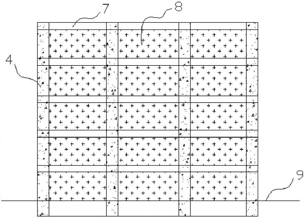
[0032] Such as figure 1 , figure 2 As shown, for the foundation pit support structure, it includes the main beam 4, the secondary beam 7, the retaining plate 8 and the anchor beam 5, the main beam 4 is longitudinally spaced on the side wall surface of the foundation pit, and the secondary beam 7 is arranged on the side wall surface of the foundation pit Horizontally spaced, the frame beam formed by connecting the main beam 4 and the secondary beam 7 is used for laying the retaining plate 8, one end of the anchor beam 5 is connected to the frame beam, and the other end extends into the side wall of the foundation pit for anchoring. Wherein the anchor beam 5 is preferably connected to the main beam 4 . In the present invention, the anchor beam 5 forms a "T"-shaped support structure relative to the main beam 4, the secondary beam 7, and the earth retain...


PUM


Abstract

The invention relates to a foundation pit support structure and a construction method of the foundation pit support structure, belonging to the technical field of foundation pit side slope support in geotechnical engineering. The foundation pit support structure in the present invention comprises a main beam, a secondary beam, a retaining plate and an anchor beam, the main beam is arranged at intervals in the longitudinal direction on the side wall surface of the foundation pit, and the secondary beams are arranged at intervals in the lateral direction on the side wall surface of the foundation pit, and the main beam and the secondary beam are mutually arranged. The frame beam formed after the connection is used for laying the retaining plate, one end of the anchor beam is connected to the frame beam, and the other end extends into the side wall of the foundation pit for anchoring, and one end of the anchoring is preferably provided with an enlarged end. The supporting structure of the foundation pit is a reinforced concrete structure as a whole. The anchor beam is preferably connected to the main beam; the junction of the anchor beam and the main beam is also provided with curved steel bars in the reinforced concrete structure. The anchor beam is preferably arranged obliquely below the sliding surface. The invention has the advantages of simple structure, high strength, good rigidity, small construction vibration and low cost, and is especially suitable for the rock-soil environment where the upper part is weak and the lower part is hard.

Description

technical field [0001] The invention relates to a foundation pit support structure and a construction method of the foundation pit support structure, belonging to the technical field of foundation pit side slope support in geotechnical engineering. Background technique [0002] In engineering construction, it is common to encounter foundation pits with the upper miscellaneous fill and the lower hard rock-soil layer, which inevitably involves the stability of foundation pit support in geotechnical engineering. The collapse of the foundation pit not only brings serious losses to the national economy, but also poses a huge threat to people's lives and property. [0003] The current foundation pit support methods mainly include soil nail anchor support, underground diaphragm wall support, sheet pile support, and row pile support. Soil nail anchoring support and underground diaphragm wall support do not require pile machine operation. During construction, the impact vibration is...

Claims


Application Information

Patent Timeline
Patent Type & Authority Applications(China)
IPC IPC(8): E02D17/04
CPCE02D17/04
Inventor 倪勇宋明健
Owner CHINA 19TH METALLURGICAL CORP
Why Eureka
Eureka Blog
Learn More