
A flow path design method for lubricating oil seal of bearing cavity

A design method and cavity lubricating oil technology, applied in the direction of engine lubrication, turbine/propulsion device lubrication, engine components, etc., can solve the problem of not considering static sealing, not being able to achieve all-round fulcrum sealing, not considering pressure control, etc. problems, to achieve the effect of reducing the probability of failure

Active Publication Date: 2019-03-22
AECC SHENYANG ENGINE RES INST
View PDF6 Cites 0 Cited by
  • Summary
  • Abstract
  • Description
  • Claims
  • Application Information

AI Technical Summary

Problems solved by technology

The specific implementation method is to bleed air from the appropriate part of the compressor to the sealing cavity of the air system, and control the pressure difference between the sealing cavity pressure of the air system and the bearing cavity within the design requirements (the pressure of the sealing cavity of the air system is higher than the pressure of the bearing cavity), In this way, the dynamic sealing of the lubricating oil in the front bearing chamber can be achieved, but this method only ensures that the air system sealing chamber pressure on one side of the dynamic seal is higher than the bearing chamber pressure, and does not consider the pressure control of the outer chamber of the front bearing chamber of the static seal, that is Only dynamic sealing is considered, static sealing is not considered, and all-round fulcrum sealing cannot be achieved

Method used


Image

  • A flow path design method for lubricating oil seal of bearing cavity
  • A flow path design method for lubricating oil seal of bearing cavity
  • A flow path design method for lubricating oil seal of bearing cavity

Examples


Embodiment Construction

[0021] In order to make the objectives, technical solutions and advantages of the present invention clearer, the technical solutions in the embodiments of the present invention will be described in more detail below in conjunction with the drawings in the embodiments of the present invention. In the drawings, the same or similar reference numerals denote the same or similar elements or elements having the same or similar functions throughout. The described embodiments are some, but not all, embodiments of the invention. The embodiments described below by referring to the figures are exemplary and are intended to explain the present invention and should not be construed as limiting the present invention. Based on the embodiments of the present invention, all other embodiments obtained by persons of ordinary skill in the art without creative efforts fall within the protection scope of the present invention.

[0022] A preferred embodiment of the flow path design method for bear...


PUM


Abstract

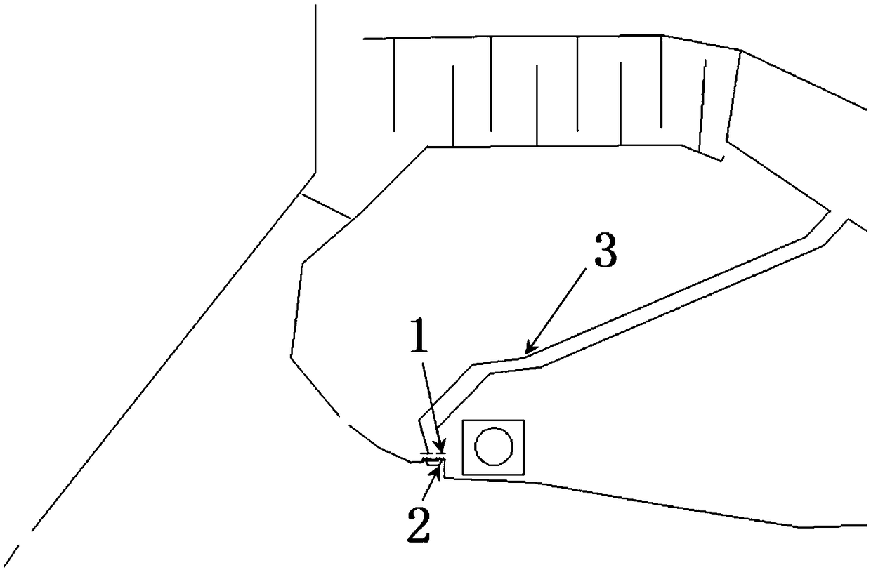
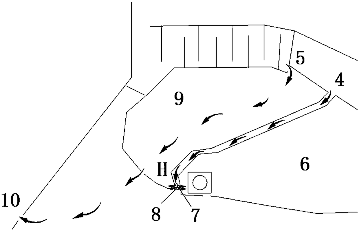
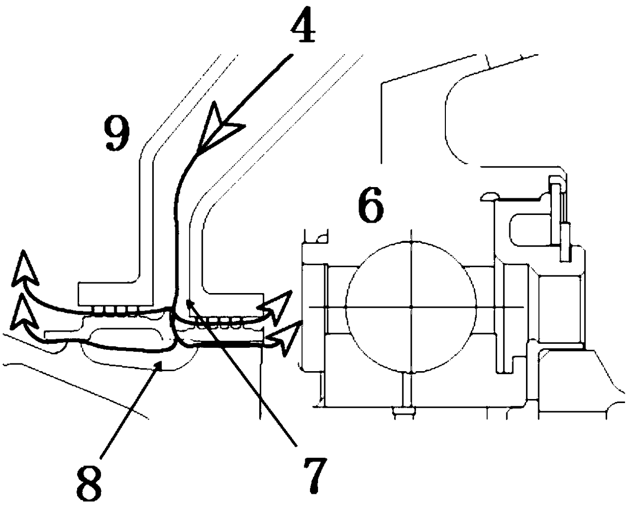
The invention provides a fluid passage design method for bearing cavity lubricating oil sealing. The fluid passage design method comprises the following steps that according to the position of a front bearing cavity and a bearing cavity peripheral structure manner, the air tight sealing position is determined, and either all positions are subject to movable sealing or fixed sealing is distinguished; the design state is determined; according to the condition obtained in the step one and the lubricating oil movable sealing tight sealing differential pressure requirement, in cooperation with aero-engine total performance parameters and component aerodynamic performance parameters, air system tight sealing fluid passage layout is carried out; parameters of all components on branch point tight sealing fluid passages are initially determined, it is guaranteed that a difference of the air system tight sealing cavity pressure used for the movable sealing and a bearing cavity pressure is within a designed and required scope, and a front bearing cavity outer cavity pressure of a fixed seal is also higher than the bearing cavity pressure; and air system analysis is carried out, the design is perfected, and the other function requirements of all fluid passages in the overall air system are met. According to the fluid passage design method, the front bearing cavity lubricating oil movable sealing and fixed sealing are considered, and all-dimensional front bearing cavity air tight sealing is achieved.

Description

technical field [0001] The invention belongs to the field of aero-engines, in particular to the field of aero-engine bearing cavities, in particular to a flow path design method for lubricating oil sealing of bearing cavities. Background technique [0002] The leakage of lubricating oil in the bearing cavity of the aeroengine will cause the rotor and stator components outside the bearing cavity to be dirty, the main channel gas pollution will cause performance loss, and the lubricating oil will enter the inner cavity of the rotating structure to cause rotor vibration, etc., which will endanger the safety and reliability of the engine. . [0003] Bearing cavity lubricating oil seal includes two aspects: dynamic seal and static seal: dynamic seal refers to the sealing of the interface with relative movement around the bearing cavity, mainly relying on dynamic seals (including grate teeth, graphite, floating rings, seal brushes, etc.) ) and the air seal design of the bearing a...

Claims


Application Information

Patent Timeline
Patent Type & Authority Patents(China)
IPC IPC(8): F02C7/06
CPCF02C7/06
Inventor 赵耘墨李俊山陆海鹰赵家军杨守辉
Owner AECC SHENYANG ENGINE RES INST
Learn More