Battery pack structure

A technology of battery packs and batteries, which is applied in the direction of secondary batteries, structural parts, battery pack components, etc., can solve the problems of cumbersome battery pack assembly process, waste of manpower and material resources, poor safety and reliability, and achieve no need for module design and Assembly process, saving time and cost, ensuring safety and reliability

Active Publication Date: 2017-06-23
ZHEJIANG LEAPMOTOR TECH CO LTD
View PDF5 Cites 1 Cited by
  • Summary
  • Abstract
  • Description
  • Claims
  • Application Information

AI Technical Summary

Problems solved by technology

[0003] The present invention mainly provides a battery pack structure with simple structure, safety and reliability, convenient and quick assembly process, and reduced manufacturing cost, which solves the cumbersome and time-consuming battery pack assembly process in the prior art, which is time-consuming and labor-intensive, and wastes a lot of manpower Technical problems such as material resources, poor safety and reliability, and inability to guarantee the quality of battery pack products
[0004] The present invention also provides a battery pack structure that can automatically expand the box body to dissipate heat outside after the temperature rise of the battery pack, which solves the problem that the heat of the battery pack in the prior art cannot be dissipated in time, which not only affects the performance of the battery Play a huge impact, but there are also technical problems such as huge security risks

Method used


Image

  • Battery pack structure
  • Battery pack structure
  • Battery pack structure

Examples


Embodiment

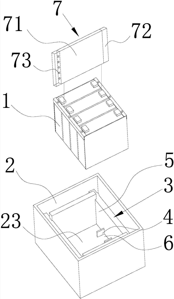
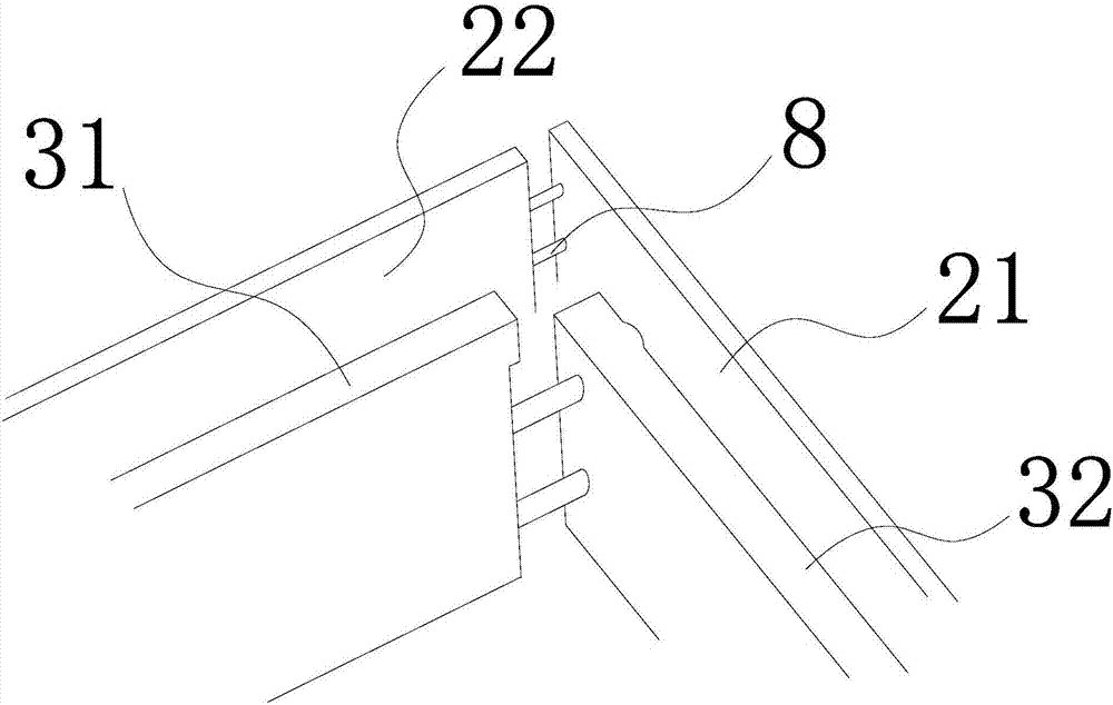
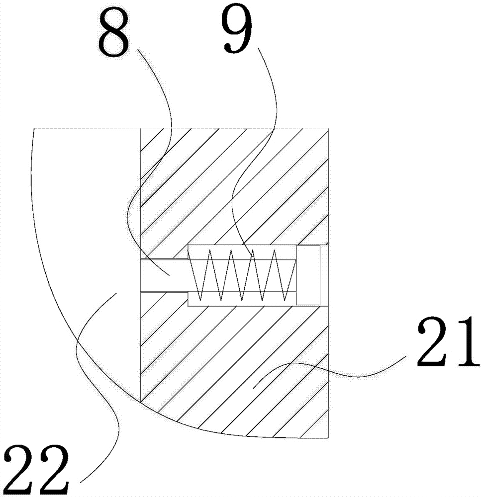
[0025] Such as figure 1 As shown, a battery pack structure of the present invention includes a rectangular box 2 for placing the battery cell 1, and the inner ring surface of the box 2 corresponding to the outer ring surface of the battery core 1 respectively extends inwardly to form an integrated battery The core fixing plate 3, the box body 2 includes the box side panel 21, the box end panel 22, the box bottom plate 23 and the box top plate, the cell fixing plate 3 includes the cell end surface fixing plates corresponding to the end faces on both sides of the cell 1 31. The cell side fixing plates 32 corresponding to the front and rear sides of the cell 1, and the box bottom plate 23 corresponding to the bottom surface of the cell 1 extends inwardly to form a number of limit bosses 4, and the limit bosses 4 extend along the line The arrangement directions of the cores 1 are distributed at equal distances. The cell fixing plate 3 and the limiting boss 4 jointly form a cell modu...


PUM


Abstract

The invention discloses a battery pack structure, and provides a battery pack structure, which has the advantages that the structure is simple, the safety and reliability are realized, the assembly process is convenient and rapid, and the manufacturing cost is reduced. The battery pack structure solves the technical problems of complicated and long assembly process of a battery pack, waste of time and labor, consumption of a large amount of manpower and material resources, poor safety and reliability, failure to ensure the quality of a battery pack product and the like in the prior art. The battery pack structure comprises a box body, wherein the box body is used for placing battery cells; the inner ring surface of the box body corresponding to the outer ring surface of each battery cell extends inwards to form a battery cell fixing plate; the bottom surface, corresponding to the bottom surfaces of the battery cells, of the box body extends inwards to form a plurality of limiting bosses; the battery cell fixing plates and the limiting bosses together define a battery cell module space, and the battery cells are assembled and installed in the battery cell module space, and are clamped into limiting grooves formed by the adjacent limiting bosses.

Description

Technical field [0001] The invention relates to a battery pack structure, in particular to a battery pack structure with simple structure, convenient and quick assembly process, and reduced manufacturing cost. Background technique [0002] The existing battery pack structure usually requires the battery cells to be assembled into a module structure first, and then the assembled module structure is assembled into a box to form a battery pack system. The assembly process is cumbersome and time-consuming, time-consuming and laborious, and wastes a lot of manpower and material resources. At the same time, due to the need for secondary assembly after transportation during the assembly process, the safety and reliability are poor, and the quality of the battery pack product cannot be guaranteed. In addition, because the existing battery pack structure often does not have a cooling structure, when the battery pack is discharged at a high rate and generates a lot of heat in some special ...

Claims


Application Information

Patent Timeline
Patent Type & Authority Applications(China)
IPC IPC(8): H01M2/02H01M10/613H01M10/6567H01M10/6556H01M50/10
CPCH01M10/613H01M10/6556H01M10/6567H01M50/10Y02E60/10
Inventor 宋忆宁姜胜利
Owner ZHEJIANG LEAPMOTOR TECH CO LTD
Why Eureka
Try Eureka