
RF connector and its insulating support

A technology of insulating support and insulator, which is applied in the direction of connection, two-part connection device, and parts of the connection device, etc. It can solve the problems of difficult assembly of connectors, and achieve the effect of simple and convenient assembly and improved precision

Active Publication Date: 2019-07-26
CHINA AVIATION OPTICAL-ELECTRICAL TECH CO LTD
View PDF9 Cites 0 Cited by
  • Summary
  • Abstract
  • Description
  • Claims
  • Application Information

AI Technical Summary

Problems solved by technology

[0003] For the use of millimeter-wave radio frequency signals with a frequency of 110GHz, there are higher requirements for its connectors and insulating supports. The Chinese patent with the announcement number CN 204927606 U and the announcement date of 2015.12.30 discloses a method for transmitting 110GHz A radio frequency connector for radio frequency signals, the connector includes an inner conductor and an outer conductor, the inner conductor is coaxially assembled in the inner hole of the outer conductor through an insulating support, the insulating support includes four U-shaped slices, and the openings of the four slices are opposite to each other Setting, the open end of the sheet is embedded on the inner wall of the outer conductor, and the arc-shaped head of the sheet encloses a star-shaped space for supporting the inner conductor. This kind of radio frequency connector needs to assemble four sheets to the size In the inner hole of the small outer conductor, it is difficult to assemble the connector

Method used


Image

  • RF connector and its insulating support
  • RF connector and its insulating support
  • RF connector and its insulating support

Examples


Embodiment Construction

[0027] Embodiments of the present invention will be further described below in conjunction with the accompanying drawings.

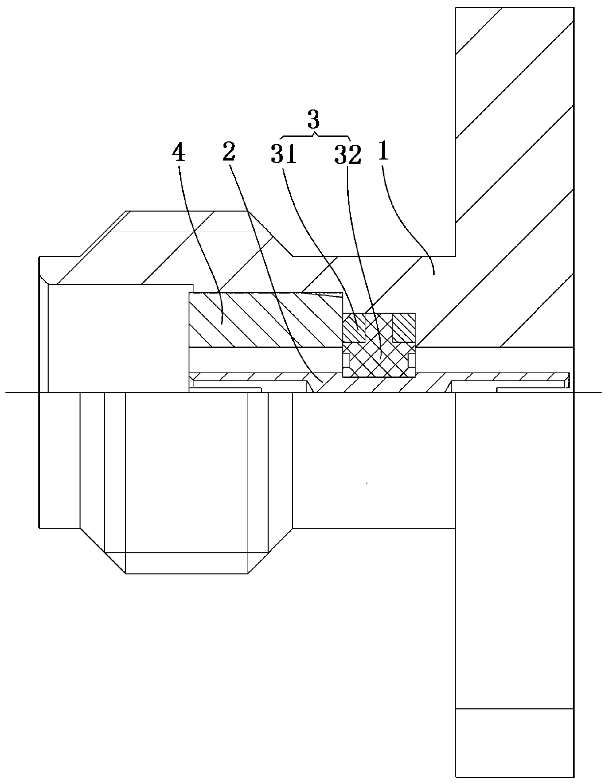
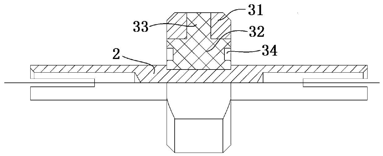
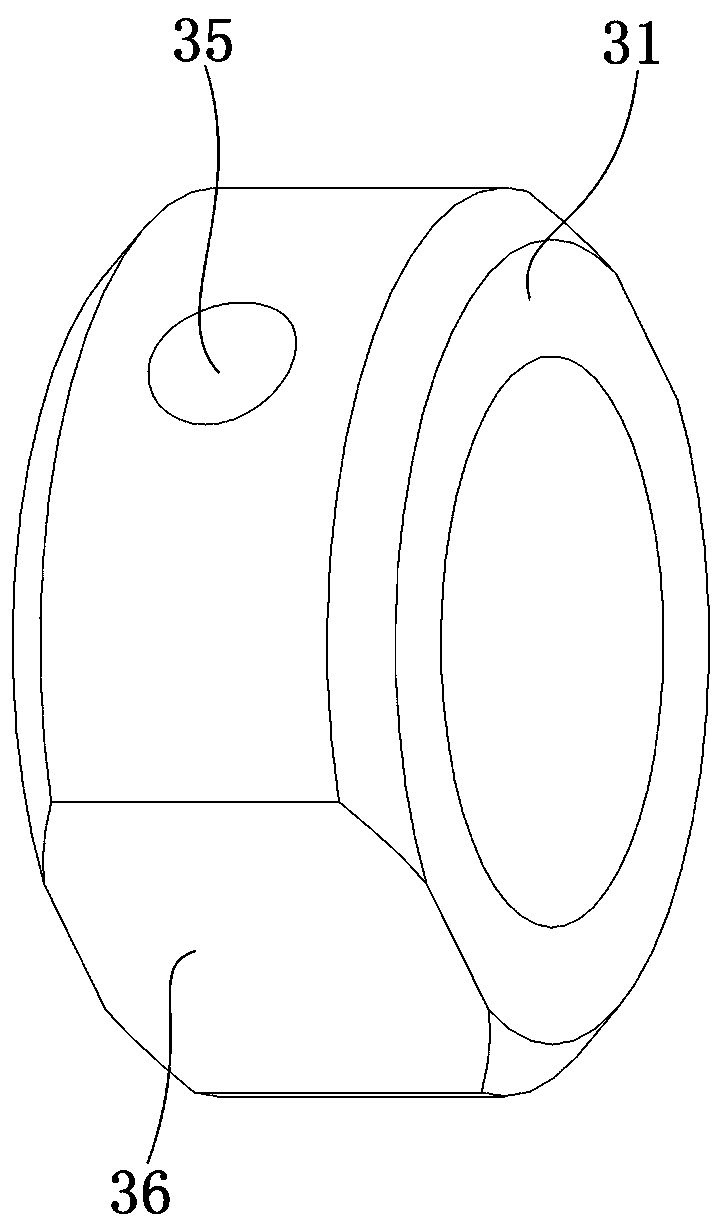
[0028] Specific embodiment 1 of the radio frequency connector of the present invention, such as Figure 1 to Figure 4 As shown, the radio frequency connector includes an outer conductor 1 , an inner conductor 2 and an insulating support 3 for supporting the inner conductor 2 in the inner hole of the outer conductor 1 . One end of the outer conductor 1 is provided with a connecting flange for connecting with an adapted printed board or other electrical components, and the other end is provided with a threaded joint for mating with an adapted connector. The insulating support 3 includes an annular base 31 and an insulator 32 disposed in the annular base 31 and molded integrally with the annular base 31 . The insulator 32 has a mounting hole for fitting on the inner conductor 2 .

[0029] The ring-shaped base 31 is a ring-shaped structure processed from a ...


PUM


Abstract

The present invention relates to a radio-frequency connector and an insulating support thereof. The radio-frequency connector comprises an internal conductor, an external conductor, and an insulating support. The internal conductor and the external conductor are coaxially mounted. The insulating support is used for supporting the internal conductor inside the inner hole of the external conductor. The insulating support comprises an annular base body and an insulator integrally injected and molded inside the inner hole of the annular base body. During assembly, the insulating support is sleeved onto the internal conductor through the installation hole of the insulator. After that, the internal conductor is installed inside the external conductor together with the insulating support. Therefore, the assembly is simple and convenient. The insulator is formed through the injection molding process. The surface precision of the installation hole of the insulator is guaranteed by a core shaft. Therefore, the precision of the installation hole of the insulator is improved.

Description

technical field [0001] The invention relates to a radio frequency connector and its insulating support. Background technique [0002] With the development of science and technology, the frequency of RF signals transmitted by RF systems is getting higher and higher, and millimeter wave RF signals have gradually become the mainstream of RF system signals. At present, there are 3.5 series, 2.92 series, 2.4 series, 1.85 series and 1.0 series of internationally accepted millimeter wave RF connectors. These millimeter-wave RF connectors have standard interfaces and inner and outer conductor sizes, and there is little difference between each R&D and production unit. The key lies in its insulating support, which must not only ensure sufficient mechanical strength, but also have good radio frequency performance. Therefore, the insulating support of millimeter wave connectors is the key and difficult point of design. [0003] The use of millimeter-wave radio frequency signals with a...

Claims


Application Information

Patent Timeline
Patent Type & Authority Patents(China)
IPC IPC(8): H01R13/42H01R13/6473H01R24/44
CPCH01R13/42H01R13/6473H01R24/44
Inventor 王小林
Owner CHINA AVIATION OPTICAL-ELECTRICAL TECH CO LTD
Learn More