Novel wireless charging reception system

A wireless charging and receiving system technology, applied in electrical components, circuit devices, grounding circuits, etc., to reduce risks, reduce system ESD risks, and reduce losses

Inactive Publication Date: 2017-06-23
苏州横空电子科技有限公司
View PDF2 Cites 6 Cited by
  • Summary
  • Abstract
  • Description
  • Claims
  • Application Information

AI Technical Summary

Problems solved by technology

[0005] The purpose of the present invention is to provide a new type of wireless charging receiving system, which aims to solve the problem that the power receiving unit cannot be well compatible and integrated with the metal shell and the EMI / ESD solution of the system, and the power receiving unit PRU cannot be configured according to different devices. The problem of self-adjustment coupling with the power transmitter unit PTU

Method used


Image

  • Novel wireless charging reception system
  • Novel wireless charging reception system

Examples


Embodiment Construction

[0023] In order to make the object, technical solution and advantages of the present invention more clear, the present invention will be further described in detail below in conjunction with the examples. It should be understood that the specific embodiments described here are only used to explain the present invention, not to limit the present invention.

[0024] The application principle of the present invention will be described in detail below in conjunction with the accompanying drawings.

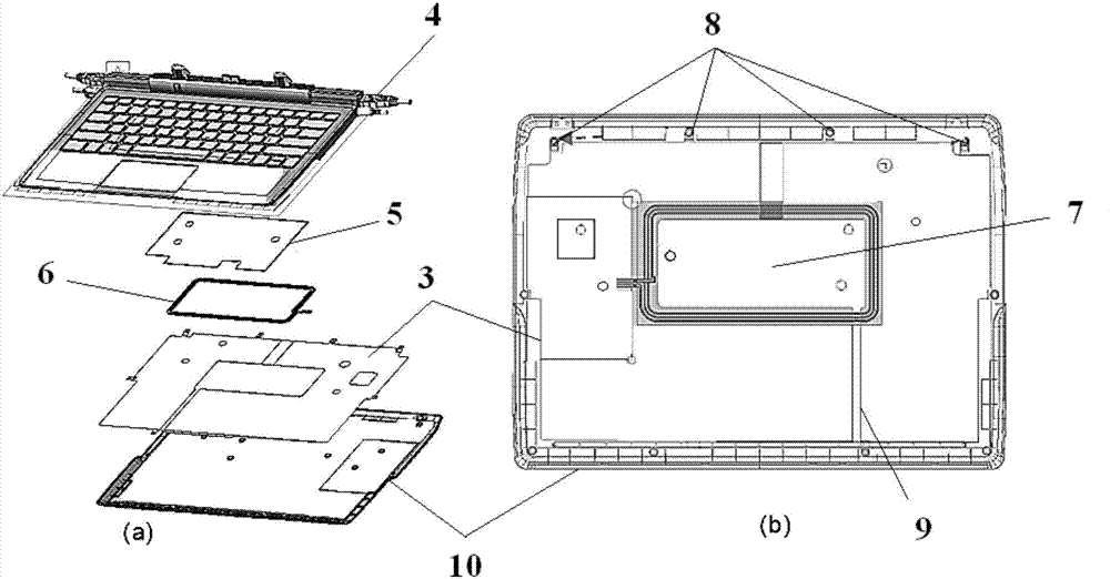
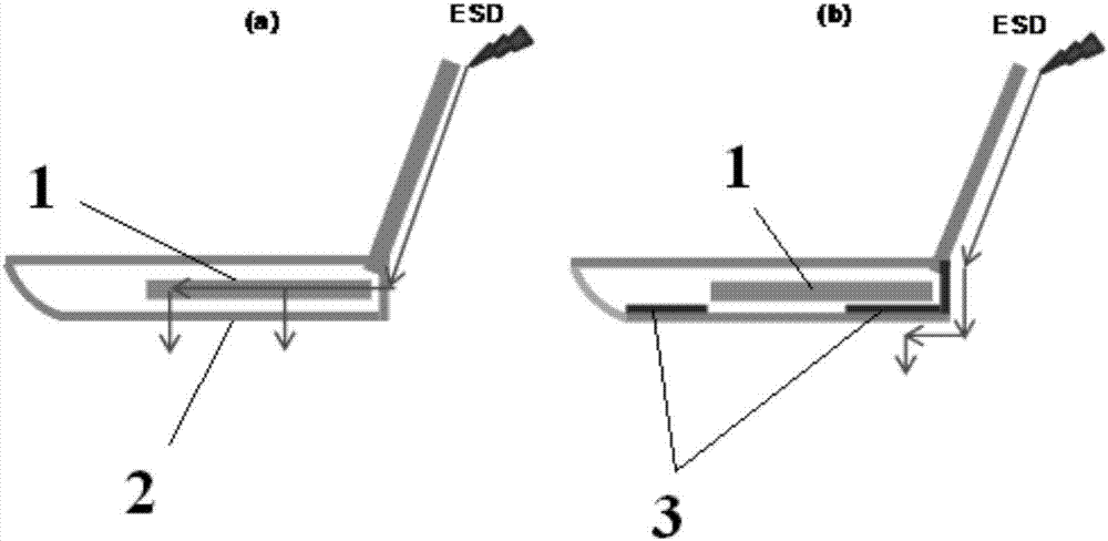
[0025] Such as figure 1 As shown, firstly, there is a long ring-shaped window in the middle of the conductive material, which allows the magnetic field of the PRU coil 6 to pass through. This window needs to be smaller than the innermost circle of the PRU coil 6, and can be adjusted in size according to the coupling requirements of the PTU and the PRU. Secondly, a slot 9 is needed, which cuts off the above-mentioned elongated annular opening, and its function is to block the generati...


PUM


Abstract

The invention discloses a novel wireless charging reception system. The system comprises a patterned conductive material layer, a long-strip annular window for adjusting coupling between PTU and PRU is arranged in a middle position of the conductive material layer, a groove which can prevent generation of an eddy current in the surrounding of a long-strip annular opening is formed in the long-strip annular window, and the tail end of the groove is grounded. According to the system, the window is formed in the surface of a high-conductivity material, and thus, magnetic-field coupling between the PTU and PRU can be controlled; adjustment can be made according to different designs of equipment; and thus, a PRU module in a wireless charging reception end can be positioned in the same position in different equipment systems, so that a wireless charging reception can be modularized in design, and is independent from design of the system and an integration environment of main equipment.

Description

technical field [0001] The invention belongs to the technical field of wireless charging, and in particular relates to a novel wireless charging receiving system. Background technique [0002] Integrating wireless charging solutions into mobile devices (such as ultrabooks, tablets, etc.) is very challenging, especially for A4WP-based resonant wireless charging solutions. The metal casing or conductive coating on the device to reduce EMI / ESD will block or absorb the magnetic field, and inside the system casing, prevent the power transmitter unit (PTU, such as a charging board) from transferring energy to the power supply through the magnetic field Receiver Unit (PRU). [0003] Depending on the configuration of the mobile device, the coupling between the same PTU and different PRUs can vary greatly from device to device. This difference makes it impossible to use a unified wireless charging PRU module for integration into different mobile systems. [0004] To sum up, in ord...

Claims


Application Information

Patent Timeline
Patent Type & Authority Applications(China)
IPC IPC(8): H02J50/10H02J50/90H02J50/70H05K9/00
CPCH05K9/0064H05K9/0067
Inventor 林森
Owner 苏州横空电子科技有限公司
Why Eureka
Try Eureka