A dry type venturi paint spray system

A Venturi and dry technology, applied in spray booths, spray devices, coatings, etc., can solve the problems of poor working environment of paint mist collection boxes, poor working environment of paint mist collection boxes, and low investment, and achieve Effects of reducing pollution and energy consumption, increasing humidity, and being easy to recycle

Active Publication Date: 2017-06-27
嘉兴启净涂装科技有限公司
View PDF7 Cites 7 Cited by
  • Summary
  • Abstract
  • Description
  • Claims
  • Application Information

AI Technical Summary

Problems solved by technology

However, the paint spraying system with this layout needs to replace the disposable paint mist collection box from the inside of the paint mist diversion chamber, and the working environment for replacing the paint mist collection box is not good
The paint spraying system of this

Method used


Image

  • A dry type venturi paint spray system
  • A dry type venturi paint spray system
  • A dry type venturi paint spray system

Examples


Embodiment 1

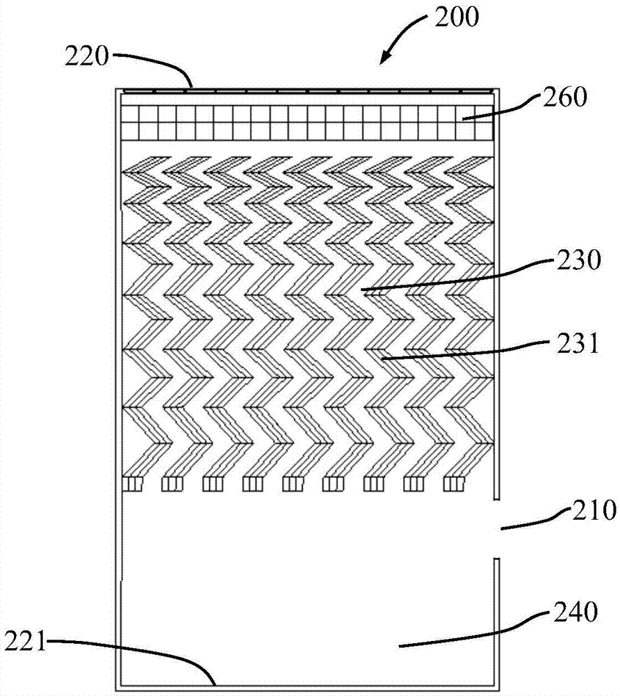
[0072] like image 3 As shown, nine paint mist trapping units 231 of the same size and shape are set in the paint mist trapping chamber 230 of this embodiment. The paint mist trapping unit is a corrugated plate structure with 13 bends, and each paint mist trap The capture unit has 1 air drainage surface and 13 bending surfaces. The bending angle of the bending surface gradually increases along the mainstream direction of the air. The 9 paint mist capture units are arranged parallel to the mainstream direction of the air, parallel to each other and Evenly distributed with equal gaps in between. The gap between two adjacent paint mist capture units forms an air flow channel with 13 bends. Since the bending angle of the paint mist capture units along the mainstream direction of the air gradually increases, the two paint mist capture units The width of the bent air flow channel formed by the gap between them also gradually narrows along the air main flow direction. The paint mis...

Embodiment 2

[0074] like Figure 4 As shown, several rows of paint mist collection units 231 are arranged in the paint mist collection chamber of this embodiment, and the distances between the paint mist collection units in the same row are the same. The five lower rows of paint mist collection units have the same size and equal row spacing, and the opening direction of the upper row of paint mist collection units and the opening direction of the next row of paint mist collection units form an angle of 60 to 90 degrees. Among the five lower rows of paint mist collection units, the gap between the next row of paint mist collection units is directly below the paint drainage heads of the upper row of paint mist collection units. The size of the paint mist collection units in the upper four rows is smaller than that in the lower five rows, and the distance between the paint mist collection units in the same row and the distance between two rows are also smaller than those in the lower five row...


PUM


Abstract

The invention provides a disposable paint mist gathering device and a dry type venturi paint spray system employing the same. The lower portion of the paint mist gathering device is provided with a paint collection chamber, the middle portion is provided with a paint mist gathering chamber, and the upper portion is provided with a sheet-like filter layer. An air inlet of the device is arranged on the upper portion on one side of the paint collection chamber, and an air outlet is arranged at the top of the paint mist gathering device. The dry type venturi paint spray system is characterized in that the disposable paint mist gathering device, as a separate part, is installed in a paint mist gathering device installing chamber. The paint mist gathering device installing chamber is arranged on the outside of an air diversion chamber. The paint mist gathering device installing chamber communicates with the air diversion chamber via a venturi channel; the venturi channel extends into the paint mist gathering device installed in place and faces the bottom of the paint mist gathering device. Compared with the prior art, the paint spray system is stable in performance, convenient to operate, great in paint mist gathering and accommodating capability, and is energy-saving and environmentally-friendly.

Description

technical field [0001] The invention relates to the field of industrial coating, especially to the field of trapping, separating and collecting sprayed overspray, in particular to a disposable dry paint mist trapping device and its applied dry Venturi paint spraying system, widely used Applied to the coating of automobiles, hardware, home appliances, toys, etc. Background technique [0002] With the rapid development of China's economy, environmental pollution has become more and more serious. In most parts of our country, human pollution of air, soil and water has far exceeded the capacity of nature. In recent years, smog has occurred frequently, and water pollution and soil pollution have become more and more serious. Painting is a highly polluting and energy-intensive industry. During the coating production process, a large amount of exhaust gas, waste liquid and solid waste will be generated. In order to maintain the constant temperature and humidity conditions requi...

Claims


Application Information

Patent Timeline
IPC IPC(8): B05B13/02B05B15/04B05B15/12
CPCB05B13/02B05B12/16B05B16/00
Inventor 周小参
Owner 嘉兴启净涂装科技有限公司
Why Eureka
Try Eureka