
Frequency tracking method for electric automobile wireless charging system

A technology of frequency tracking and wireless charging, applied in electric vehicle charging technology, electric vehicles, charging stations, etc., can solve the problem of low charging efficiency and achieve high charging efficiency

Inactive Publication Date: 2017-06-27
CHINA UNIV OF PETROLEUM (EAST CHINA)
View PDF5 Cites 17 Cited by
  • Summary
  • Abstract
  • Description
  • Claims
  • Application Information

AI Technical Summary

Problems solved by technology

[0009] The invention provides a frequency tracking method for an electric vehicle wireless charging system, which mainly solves the problem of low charging efficiency caused by external interference when the existing electric vehicle wireless charging system is charging

Method used


Image

  • Frequency tracking method for electric automobile wireless charging system
  • Frequency tracking method for electric automobile wireless charging system
  • Frequency tracking method for electric automobile wireless charging system

Examples


Embodiment 1

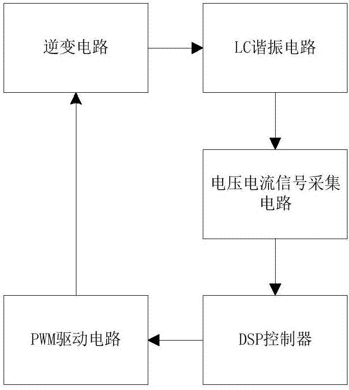
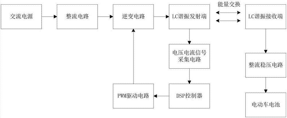
[0024] Embodiment 1, the wireless charging frequency tracking system of this embodiment, such as figure 1 Shown, including: high-frequency inverter circuit, LC resonant circuit, frequency tracking circuit. The high-frequency inverter circuit is used to generate a high-frequency current consistent with the frequency of the LC resonant circuit to resonate the entire system; the LC resonant circuit is used to form a resonant system to transfer energy to maximize charging efficiency; the frequency tracking circuit is used to capture voltage and current The phase difference is used as the PWM driving signal of the high-frequency inverter circuit after a series of adjustments.

[0025] The high-frequency inverter circuit includes a MOS tube full-bridge inverter circuit and a PWM drive circuit. The PWM drive circuit is used to amplify the voltage signal output by the phase-locked loop and supply it to the MOS transistor full-bridge inverter circuit to change the output frequency; th...

Embodiment 2

[0028] Embodiment 2, the wireless charging frequency tracking method of this embodiment, such as image 3 As shown, the wireless charging frequency tracking device shown in the above-mentioned embodiment 1 is used to realize, including the following steps:

[0029] S1, using the voltage and current detection circuit and the phase capture operation of the DSP controller to capture the phase of the fundamental wave of the voltage and current;

[0030] S2. Using the phase difference captured by the DSP controller to perform proportional integral calculation adjustment to obtain the frequency deviation;

[0031] S3, using the DSP controller to adjust the frequency deviation to obtain a PWM signal consistent with the frequency of the transmitter circuit;

[0032] S4. Input the PWM signal into the high-frequency inverter circuit to make the whole system resonate.


PUM


Abstract

The invention provides a frequency tracking method for an electric automobile wireless charging system and relates to the field of wireless charging. According to the frequency tracking method, the problem that the charging efficiency of an existing electric automobile wireless charging system is low at the time of charging due to external disturbance is mainly solved. The system comprises a high-frequency inverting circuit, an LC resonance circuit and a frequency tracking circuit. The high-frequency inverting circuit is used for producing a high-frequency signal consistent with the LC resonance circuit in frequency to enable the whole system to resonate. The frequency tracking circuit is used for detecting the voltage and current phase of a wireless transmitting terminal and outputting a PWM driving signal to the high-frequency inverting circuit after a series of adjustments. The LC resonance circuit is used for constituting a resonance system and guaranteeing efficient energy transmitting. The method comprises the steps that voltage and current signals are collected to conduct FFT transformation to obtain a phase difference; the phase difference is subjected to PI operation through phase locking treatment to obtain an adjusted frequency; and the adjusted frequency serving as the frequency of the PWM driving signal of the high-frequency inverting circuit produces a high-frequency current to form the resonance system to transmit energy. The resonance frequency of the system is tracked through the method of a resonance-type phase-locked loop of a voltage and current fundamental harmonic phase, and it can be effectively ensured that the system keeps the resonance state and has high charging efficiency.

Description

[0001] 【Technical field】 [0002] The invention relates to the field of wireless charging, in particular to a frequency tracking method for a magnetic coupling resonant wireless charging system of an electric vehicle. [0003] 【Background technique】 [0004] At present, the earth's fossil fuel resources are in short supply and the environment is seriously polluted. Electric vehicles (EVs), as green and environment-friendly vehicles, will gradually replace traditional fuel vehicles to dominate the automobile market. [0005] The key to the widespread use of electric vehicles is the continuation of battery power. The existing charging methods are on-board chargers and external charging piles, both of which are wired charging methods. Disadvantages of wired charging, such as: easy to generate sparks, easy to wear, difficult to maintain, and plug-in charging can only charge one car at a time, and the high output voltage of the charger will cause a series of safety problems. [00...

Claims


Application Information

Patent Timeline
IPC IPC(8): B60L11/18
CPCB60L53/12Y02T10/72Y02T10/70Y02T10/7072Y02T90/14
Inventor 张磊潘文凯高春侠徐金海
Owner CHINA UNIV OF PETROLEUM (EAST CHINA)
Learn More