
Large power composite ultraphonic pipe

A composite ultrasonic and composite tube technology, which is applied in the direction of sound-generating devices, instruments, chemical instruments and methods, etc., can solve the problems of limited total output power of cylindrical transducers, low vibration energy conversion efficiency, and the circular tube should not be too long. , achieve significant internal heating, high electro-acoustic efficiency, and improve electromechanical conversion efficiency

Inactive Publication Date: 2012-07-25
ZHEJIANG NORMAL UNIVERSITY
View PDF6 Cites 0 Cited by
  • Summary
  • Abstract
  • Description
  • Claims
  • Application Information

AI Technical Summary

Problems solved by technology

[0006] (2) For ultrasonic rod transducers with lower frequencies, their lateral dimensions (diameters) will be relatively large, which limits their application range
There is a problem with energy conversion efficiency compared to a single vibration mode
Generally, the vibration energy conversion efficiency of mode conversion is lower than that of a single vibration mode transducer
[0013] (2) The circular tube can only be driven by the longitudinal composite transducers at both ends, so the total output power of the cylindrical transducer is limited
In addition, the length of the circular tube must meet the integer multiple of half wavelength, and the circular tube should not be too long, otherwise, the efficiency of the transducer will be low

Method used


Image

  • Large power composite ultraphonic pipe
  • Large power composite ultraphonic pipe
  • Large power composite ultraphonic pipe

Examples


Embodiment Construction

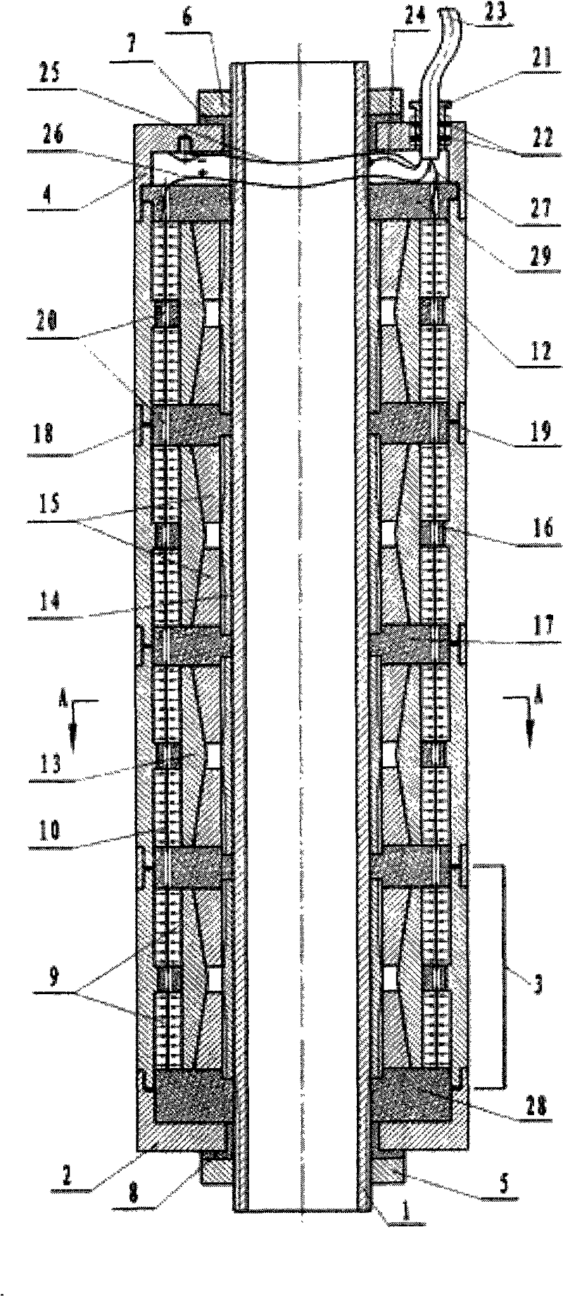
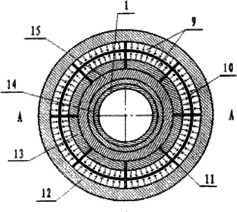
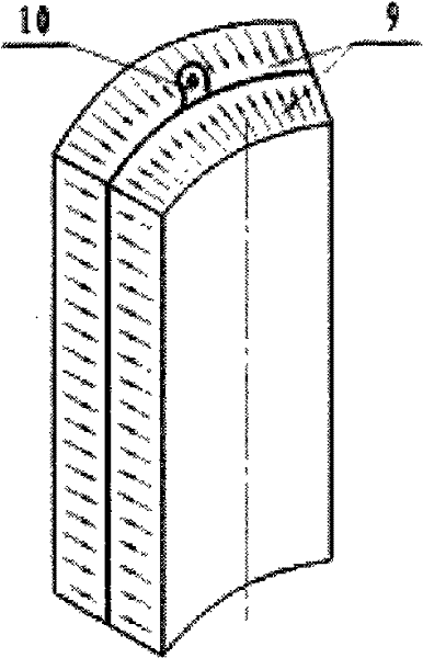
[0033] Such as figure 1 As shown, a high-power composite ultrasonic tube consists of a hollow threaded tube 1 passing through the end cap 2 with a central through hole and four short composite tube piezoelectric transducer units 3, and then passing through the central through hole of the end cap 4 , use nuts 5 and 6 to tighten the connection at both ends respectively. Waterproof sealing rings 7 and 8 are arranged between the central through holes of the end caps 2 and 4 and the hollow threaded pipe 1 and the nuts 5 and 6 . Each short composite tube piezoelectric transducer unit 3 contains two sets of cylindrical piezoelectric ceramic stack ring groups, such as figure 2 As shown: each group of cylindrical piezoelectric ceramic stack rings consists of eight cylindrical piezoelectric ceramic stack units uniformly arranged in a ring along the circumference, as shown in image 3 As shown: each cylindrical piezoelectric ceramic stack unit is stacked by two arc-shaped piezoelectri...


PUM


Abstract

The invention relates to a large power composite ultraphonic pipe. A long composite ultraphonic pipe is formed in such a way that a plurality of short composite pipe piezoelectric transducer units are connected along the axial direction by hollow thread pipes; both ends of the long composite ultraphonic pipe are provided with covers; each short composite pipe piezoelectric transducer unit comprises at least one cylindrical surface piezoelectric pile ring group; the outer parts of the cylindrical surface piezoelectric pile ring groups are provided with metal prestress shells; the outer walls of the cylindrical surface piezoelectric pile ring groups and the inner walls of the metal prestress shells are tightly compounded together; the inner parts of the cylindrical surface piezoelectric pile ring groups are provided with expanding type prestress mechanisms; the two adjacent expanding type prestress mechanisms are electrically connected; the metal prestress shells of the two adjacent short composite pipe piezoelectric transducer units are electrically connected; cylindrical surface piezoelectric pile units in each cylindrical surface piezoelectric pile ring group are electrically connected, and the two adjacent cylindrical surface piezoelectric pile ring groups are electrically connected. The large power ultraphonic pipe can generate even cylindrical surface sound radiation in the radial omnidirectional range and is particularly suitable for the ultraphonic processing of liquid.

Description

technical field [0001] The invention relates to an ultrasonic device, in particular to a high-power composite ultrasonic tube capable of producing omnidirectional cylindrical radiation. Background technique [0002] With its advantages of high power density, high electromechanical conversion efficiency and stable performance, the composite ultrasonic transducer has been widely used in ultrasonic cleaning, ultrasonic welding, ultrasonic vibration cutting and processing, etc. Sandwich type longitudinal composite ultrasonic transducer, etc. [0003] High-power ultrasound has broad application prospects in the field of liquid ultrasonic treatment technology. Liquid ultrasonic treatment technology is an energy-saving and environmentally friendly green ultrasonic application technology that uses ultrasonic vibration energy to produce physical effects such as cavitation, radiation pressure, and acoustic flow in liquid media to process liquids. For example, in the field of sonoche...

Claims


Application Information

Patent Timeline
Patent Type & Authority Patents(China)
IPC IPC(8): G10K9/122B08B3/12
Inventor 刘世清方健文张志良
Owner ZHEJIANG NORMAL UNIVERSITY
Learn More