
Four-rotor-wing unmanned aerial vehicle with independent and controllable space six freedom degrees and control method thereof

A technology of unmanned aerial vehicle and degree of freedom, which is applied in the fields of UAV, UAV flight mechanics and control, and can solve the problems of increasing the structure, increasing the complexity of the aircraft, and the unchangeable pitch of the propeller.

Active Publication Date: 2017-06-27
NANJING UNIV OF AERONAUTICS & ASTRONAUTICS
View PDF7 Cites 24 Cited by
  • Summary
  • Abstract
  • Description
  • Claims
  • Application Information

AI Technical Summary

Problems solved by technology

[0003] At present, most multi-rotor UAVs use propellers to provide lift. Since the propellers are not variable pitch, changing the pulling force is achieved by adjusting the motor speed, and because the direction of the propeller pulling force cannot be tilted relative to the fuselage, so whether it is flying forward Or changing the heading will inevitably lead to a change in the attitude of the fuselage, that is, there is a problem of coupling speed and attitude
In the case that the fuselage needs to be constantly tilted, the stability of the flight is affected, and the instruments and equipment work on a shaking platform, so it is difficult to achieve the best results
In order to eliminate this instability, stabilized gimbals such as three-axis stabilized gimbals are generally used, but unnecessary structures are added, and the requirements for the control system are relatively high, which undoubtedly increases the complexity of the aircraft.

Method used


Image

  • Four-rotor-wing unmanned aerial vehicle with independent and controllable space six freedom degrees and control method thereof
  • Four-rotor-wing unmanned aerial vehicle with independent and controllable space six freedom degrees and control method thereof
  • Four-rotor-wing unmanned aerial vehicle with independent and controllable space six freedom degrees and control method thereof

Examples


Embodiment 1

[0095] This embodiment introduces the implementation of vertical take-off, hovering at zero attitude angle, and vertical landing of the present invention.

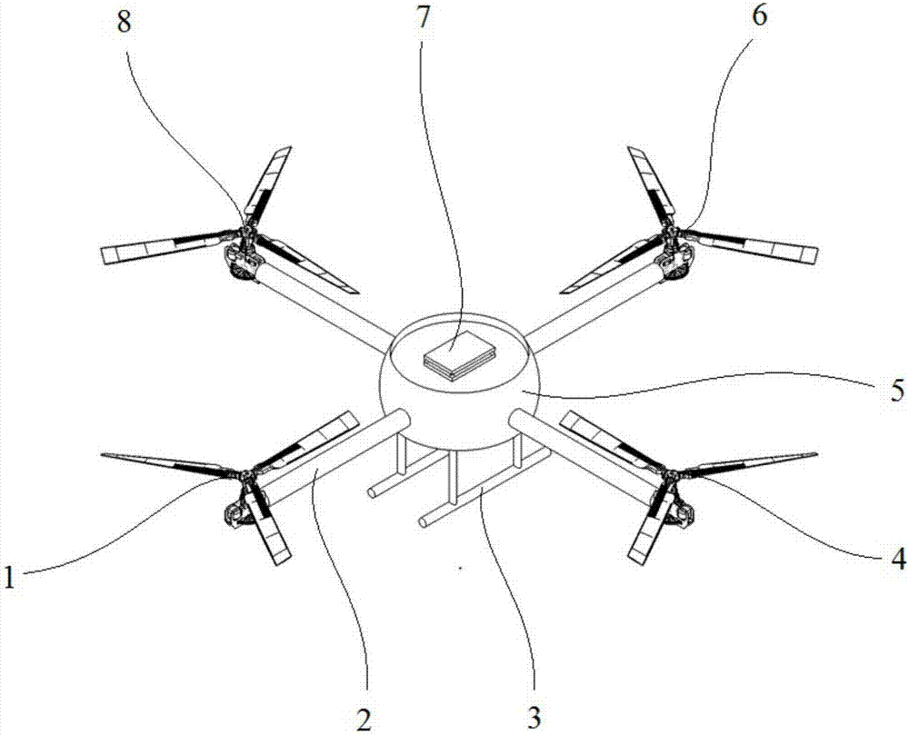
[0096] like Image 6 As shown, the four rotors, including the front rotor, rear rotor, left rotor, and right rotor, can realize the vertical takeoff, zero attitude hovering and vertical landing of the aircraft through the synchronous control of the collective distance of the front and rear rotors and the synchronous control of the collective distance of the left and right rotors. , the specific process is: the aircraft is parked on the level ground or platform, and the motor 16 drives the four rotors to rotate after the power is turned on. The controller 7 receives the input of 6 channels of the aircraft, and the input of other channels is zero except for the up and down speed input. According to The multi-variable decoupling control algorithm with six degrees of freedom in space solves the control commands of 12 steering ...

Embodiment 2

[0099] This embodiment introduces the implementation of the present invention to fly forward at zero attitude angle.

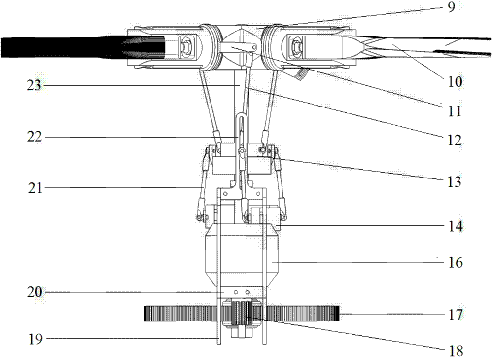
[0100] On the basis of Embodiment 1, the aircraft reaches the zero-attitude hovering state, and the controller 7 receives 6 channel inputs of the aircraft. Except for the front and rear speed inputs, other channel inputs are all zero, and the 6-channel input is used as the flight state expectation value, according to The multi-variable decoupling control algorithm with six degrees of freedom in space calculates and obtains the control commands of all 12 steering gears and the speed commands of 4 motors under the expected value of the flight state, controls the rotation angle of the rocker arm 15 of the steering gear, and controls the rotation speed through the motor speed. The rotational speed of the rotor is to realize the desired control of the automatic tilter 13 on the rotor by the up and down pull rod, so as to realize the forward flight of the aircraft at...

Embodiment 3

[0102] This embodiment introduces the implementation of hovering at any attitude angle in the present invention.

[0103] On the basis of Embodiment 1, the aircraft reaches the zero-attitude hovering state, such as Figure 8 As shown, under the action of the controller 7, through the collective pitch differential control of the front and rear rotors and the collective pitch differential control of the left and right rotors, the pitching moment and rolling moment can be generated respectively for the center of gravity, and the fuselage 5 can realize the corresponding pitching, rolling, and rolling moments. Rolling action, at this time, cooperate with the synchronous control of the longitudinal periodical variable pitch of the front and rear rotors, and the synchronous control of the lateral periodical variable pitch of the left and right rotors, so that the pulling force of the rotor is always kept vertically upward, and the sum of the four pulling forces is equal to the gravity...


PUM


Abstract

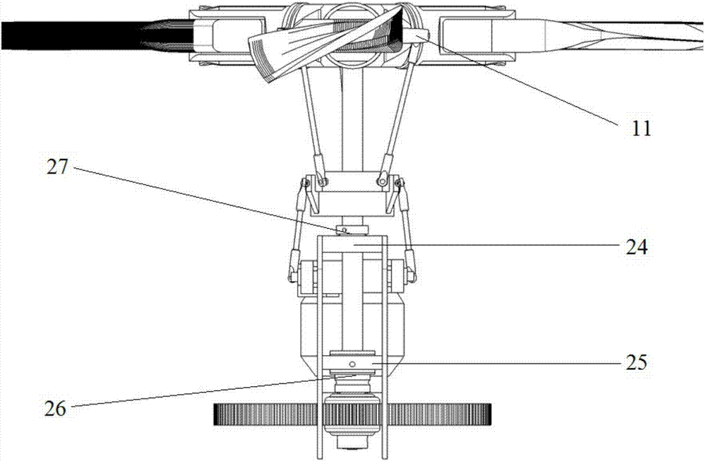
The invention discloses a four-rotor-wing unmanned aerial vehicle with independent and controllable space six freedom degrees and a control method thereof. The four-rotor-wing unmanned aerial vehicle comprises a vehicle body, vehicle arms and a controller. The four vehicle arms are fixed to the vehicle body. The tail ends of the vehicle arms are provided with multi-freedom-degree controllable rotor wing nacelle systems. Rotor wings adopt central hinge type propeller hubs and are driven by motors. The pitches and the rotating speeds of the rotor wings can be changed. Steering engines control automatic inclinators to achieve total pitch and cyclic pitch control over the rotor wings. Propeller discs can overturn in any direction under control of the steering engines. The total pitches, longitudinal and transverse cyclic pitches and rotating speeds of all the rotor wings are independently controlled. Each pair of rotor wings provides force in three directions and torque in three directions, and through combination coordination of the four pairs of rotor wings, the six freedom degrees (three linear speeds and three attitude angles) of the aerial vehicle flying in the sky can be decoupled, and the speed and posture of the aerial vehicle are independent and controllable. The aerial vehicle has input of six channels, namely a front-rear speed, a left-right speed, an up-down speed, a pitch attitude, a rolling attitude and a heading attitude which separately correspond to the six freedom degrees of the aerial vehicle.

Description

technical field [0001] The invention relates to the technical field of unmanned aerial vehicles, in particular to a six-degree-of-freedom decoupling control technology for a multi-rotor aircraft, and specifically belongs to the technical field of unmanned aerial vehicle flight mechanics and control. Background technique [0002] The multi-rotor aircraft utilizes multiple rotors, can fly in any direction and hover in the air, and can complete various tasks. For example, use a multi-rotor drone to carry a miniature camera for aerial photography, or carry various measuring instruments for high-altitude detection or throwing objects. Today, multi-rotor aircraft have been widely used in many fields such as agriculture, meteorology, electric power, disaster warning and rescue. [0003] At present, most multi-rotor UAVs use propellers to provide lift. Since the propellers are not variable pitch, changing the pulling force is achieved by adjusting the motor speed, and because the d...

Claims


Application Information

Patent Timeline
Patent Type & Authority Applications(China)
IPC IPC(8): B64C27/08B64C27/14B64C27/59
CPCB64C27/08B64C27/14B64C27/59B64U10/10B64U50/19B64U2201/10
Inventor 宋彦国王焕瑾陈忠俊
Owner NANJING UNIV OF AERONAUTICS & ASTRONAUTICS
Learn More