Hydraulic cast steel sluice valve

A technology of cast steel and gate valve, applied in the field of hydraulic cast steel gate valve, can solve the problem that the gate valve does not have the anti-return function, cannot prevent the fluid from retrograde, etc., and achieves the effect of good sealing effect, preventing valve blockage and preventing locking.

Inactive Publication Date: 2017-06-27
TIANJIN NIUWEI VALVE TECH DEV
View PDF9 Cites 4 Cited by
  • Summary
  • Abstract
  • Description
  • Claims
  • Application Information

AI Technical Summary

Problems solved by technology

The existing gate valves have the following problems during use: the gate valve does not have a non-return function and cannot prevent fluid from reversing

Method used


Image

  • Hydraulic cast steel sluice valve

Examples


Embodiment

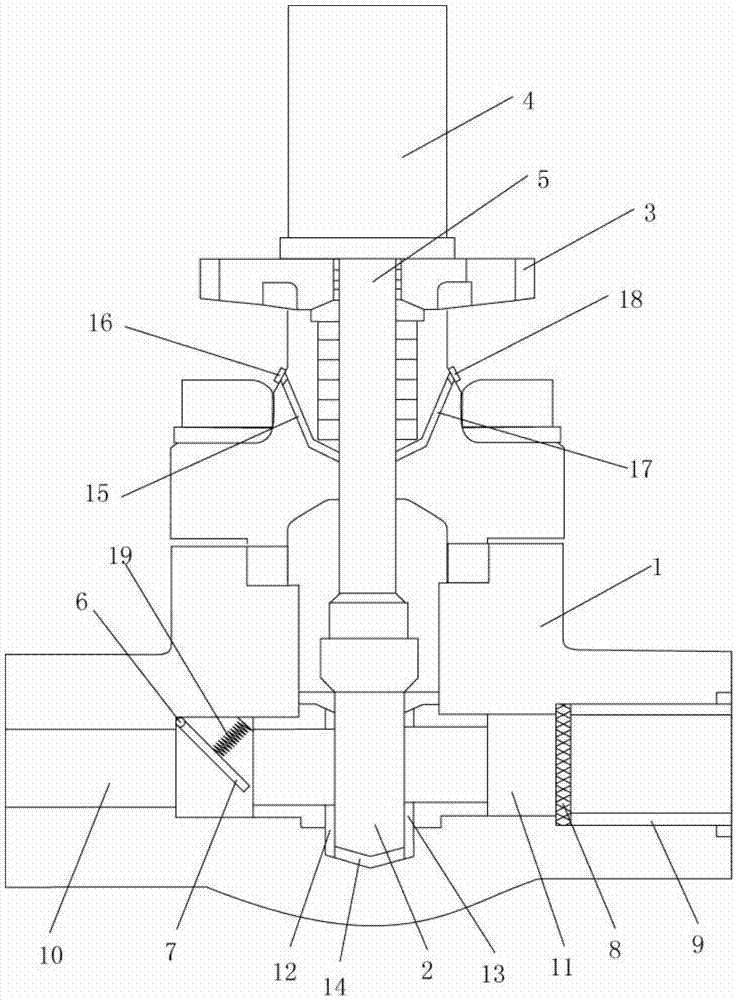
[0020] Such as figure 1 As shown, a hydraulic cast steel gate valve includes a valve body 1, a gate plate 2, a valve cover 3, a hydraulic cylinder 4, a valve stem 5, a rotating shaft 6, a check plate 7, a filter screen 8, a compression sleeve 9, and a spring 19 One end of the valve body 1 is provided with a fluid inlet 10 and the other end is provided with a fluid outlet 11, the middle part of the valve body 1 is provided with a gate 2, and the contact part between one side of the gate 2 and the valve body 1 is provided with a first seal Ring 12, the second sealing ring 13 is provided at the contact part between the other side of the gate 2 and the valve body 1, the third sealing ring 14 is provided at the contact part between the bottom of the gate 2 and the valve body 1, and the valve cover 3 is fixed on On the top of the valve body 1, the hydraulic cylinder 4 is fixed on the valve cover 3. One end of the valve stem 5 is connected to the hydraulic cylinder 4 and the other en...


PUM


Abstract

The invention belongs to the field of valves and particularly relates to a hydraulic cast steel sluice valve. The hydraulic cast steel sluice valve is characterized in that a first sealing ring is installed on the position, making contact with a valve body, of one side of a flashboard, a second ring is installed on the position, making contact with the valve body, of the other side of the flashboard, and a third sealing ring is installed on the position, making contact with the valve body, of the bottom of the flashboard; a valve cover is fixed at the top of the valve body, and a hydraulic cylinder is fixed to the valve cover; one end of a valve rod is connected with the hydraulic cylinder, and the other end of the valve rod is connected with the upper end of the flashboard; a first oil filling port leading towards the valve rod is formed in one side of the valve body, and a second oil filling port leading towards the valve rod is formed in the other side of the valve body; the upper end of a non-return plate is installed on a rotary shaft, one end of a spring is connected with the middle of the non-return plate, and the other end of the spring is fixed to the inner wall, corresponding to the non-return plate, of a fluid inlet; and a filter net is fixed to the interior of a fluid outlet and pressed through a pressing sleeve.

Description

technical field [0001] The invention belongs to the field of valves, in particular to a hydraulic cast steel gate valve. Background technique [0002] The valve is a control component in the fluid delivery system, which has functions such as cut-off, adjustment, flow diversion, reverse flow prevention, pressure stabilization, flow diversion or overflow pressure relief. Gate valve is a commonly used valve. There is an opening and closing gate inside the gate valve. The direction of movement of the gate is perpendicular to the direction of the fluid. The gate valve is fully open and fully closed. It can be widely used in tap water, sewage, construction, petroleum, It is used as a regulating and intercepting device on the pipelines of chemical industry, food, medicine, light textile, electric power, shipbuilding, metallurgy, energy system, etc. The existing gate valve has the following problems during use: the gate valve does not have a non-return function, and cannot prevent ...

Claims


Application Information

Patent Timeline
Patent Type & Authority Applications(China)
IPC IPC(8): F16K3/02F16K3/314F16K31/12F16K3/30F16N1/00B01D35/04F16K3/32F16K15/03
CPCF16K3/0209F16K3/0227F16K3/30F16K3/314F16K3/32F16K15/033F16K31/12F16N1/00
Inventor 洪春龙洪昆生
Owner TIANJIN NIUWEI VALVE TECH DEV
Why Eureka
Try Eureka