Steel rail centering device

A technology of steel rails and middle rods, which is applied in the direction of measuring devices, mechanical measuring devices, and mechanical devices, etc. It can solve the problems of inconvenient handling, low measurement efficiency, and long time-consuming, etc., and achieves simple structure, guaranteed measurement accuracy, and easy operation. convenient effect

Active Publication Date: 2017-06-27
ZHUZHOU TIMES ELECTRONICS TECH CO LTD
View PDF16 Cites 2 Cited by
  • Summary
  • Abstract
  • Description
  • Claims
  • Application Information

AI Technical Summary

Problems solved by technology

This method takes a long time, the measurement efficiency is not high, and because the bracket and the ruler support are long, it is not convenient to carry when the vehicle needs to go up and down the road.

Method used


Image

  • Steel rail centering device
  • Steel rail centering device
  • Steel rail centering device

Examples


Embodiment Construction

[0037] In order to make the purpose, technical solutions and advantages of the embodiments of the present invention more clear, the technical solutions in the embodiments of the present invention will be clearly and completely described below in conjunction with the drawings in the embodiments of the present invention. Apparently, the described embodiments are only some of the embodiments of the present invention, not all of them. Based on the embodiments of the present invention, all other embodiments obtained by persons of ordinary skill in the art without creative efforts fall within the protection scope of the present invention.

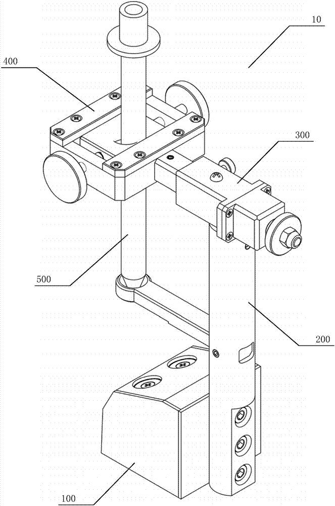
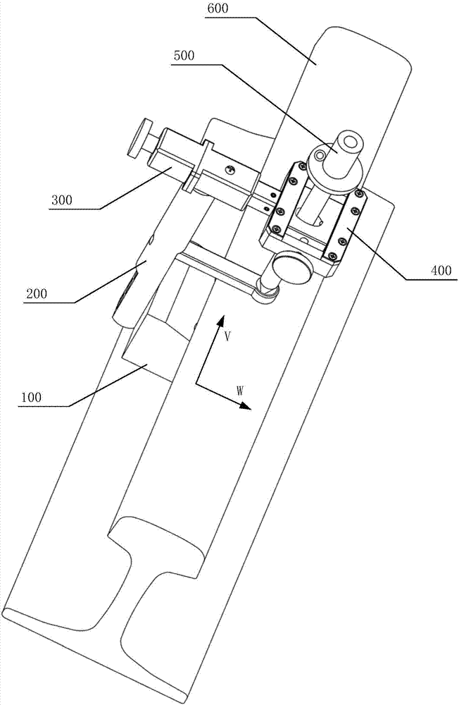
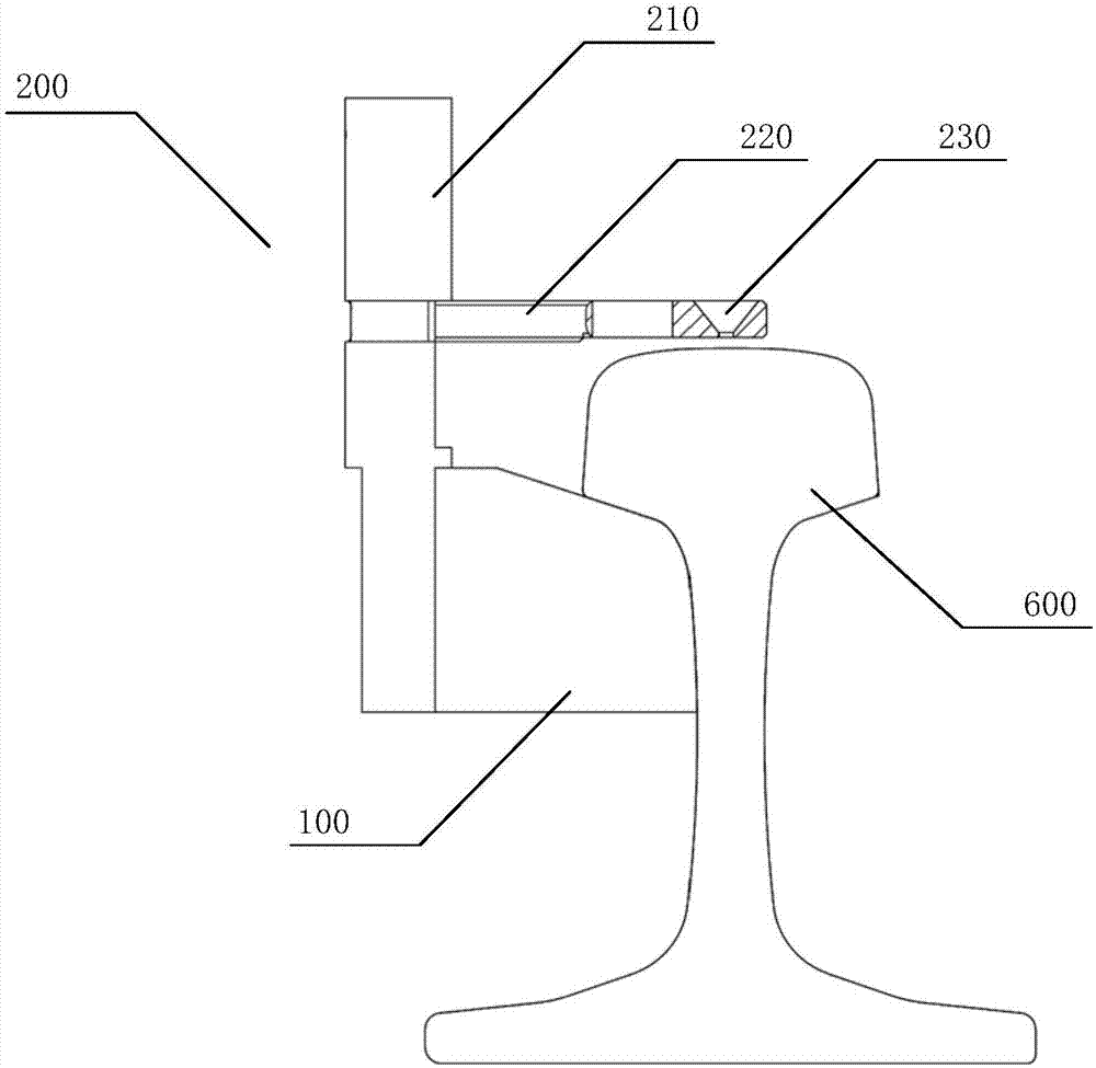
[0038] as attached figure 1 to attach Figure 15 As shown, specific embodiments of the rail centering device of the present invention are provided, and the present invention will be further described below in conjunction with the accompanying drawings and specific embodiments.

[0039] as attached figure 1As shown, a specific embodiment of a r...


PUM


Abstract

The invention discloses a steel rail centering device comprising a suction base, a centering bracket, a lateral adjustment mechanism, a vertical adjustment mechanism and a centering rod. The suction base is fixed to the side of a unilateral steel rail. The centering bracket further includes a support bar and a pallet. The bottom of the support bar is fixed to the suction base. The pallet is fixed on the support bar and is located at the upper part on the top surface of the steel rail. A tapered hole is arranged in the pallet. The lateral adjustment mechanism is fixed to the upper part of the support bar. The vertical adjustment mechanism is fixed to the end of the lateral adjustment mechanism. The centering rod is fixed on the vertical adjustment mechanism. The lateral adjustment mechanism is used to adjust the lateral position of the centering rod on the top surface of the steel rail. The vertical adjustment mechanism is used to adjust the vertical position of the centering rod on the top surface of the steel rail. The bottom of the centering rod is located in the tapered hole. The steel rail centering device of the invention is applicable to various line conditions, and can quickly find the position of the center point of the top surface of the unilateral steel rail and the vertical direction of the point, thereby realizing the rapid measurement and improving the measurement efficiency.

Description

technical field [0001] The invention relates to the technical field of track engineering machinery, in particular to a rail centering device applied to railway line measurement. Background technique [0002] In order to improve the efficiency of railway operation and maintenance and realize efficient and automated railway maintenance, the railway engineering department usually needs to measure the position of the center point of the top surface of the rail, and process the coordinate data obtained from the measurement, and the processed data is used for railway lines maintain. At present, the railway engineering department mostly detects the position of the rail in the following two ways: [0003] (1) The first method is to use a total station for measurement, and obtain the coordinates by measuring the reflective prism with the total station. In order to obtain the coordinates of the center point of the top surface of the rail in this way, the reflective prism must be fix...

Claims


Application Information

Patent Timeline
Patent Type & Authority Applications(China)
IPC IPC(8): G01B5/00
CPCG01B5/00
Inventor 朱利君周利文何奎元曹辉王文昆管建民
Owner ZHUZHOU TIMES ELECTRONICS TECH CO LTD
Why Eureka
Try Eureka