Power transfer device, photosensitive element and processing cartridge

A power transmission device and power transmission technology, which are applied in the directions of optics, electrography, instruments, etc., can solve the problems such as the inability to realize the power receiving port 12 and the limitation of the scope of application of the processing box.

Active Publication Date: 2017-06-27
ZHONGSHAN KINGWAY IMAGE TECH CO LTD
View PDF10 Cites 7 Cited by
  • Summary
  • Abstract
  • Description
  • Claims
  • Application Information

AI Technical Summary

Problems solved by technology

[0006] However, after the process cartridge C is loaded into the printer, the end of the pressing rod 13 connected to the spring 18 is a free end suspended outside, and the external force F comes from the printer door, that is to say, the power receiving port 12 Extending out requires the help of the printer door. It must be ensured that the printer door is closed along the Y direction and can touch the pressing rod 13, and the printer door can continuously apply force to the pressing rod 13. When the printer door is loose, Even if the printer door can touch the pressing rod 13, it cannot provide continuous active force to the pressing rod 13, and the stretching of the power receiving port 12 will not be realized; when the closing direction of the printer door is perpendicular to the X direction and the Y direction During the -Z direction, the printer cover door will not be able to touch the pressing rod 13, therefore, the power receiving port 12 will not stretch out, and the scope of application of the process box provided with the power receiving port 12, pressing rod 13 and spring 18 is limited. extremely restrictive

Method used


Image

  • Power transfer device, photosensitive element and processing cartridge
  • Power transfer device, photosensitive element and processing cartridge
  • Power transfer device, photosensitive element and processing cartridge

Examples


Embodiment Construction

[0032] Combine below Figure 3-Figure 8 , Figure 9A , Figure 9B , Figure 10A and Figure 10B Embodiments of the present invention are described in detail.

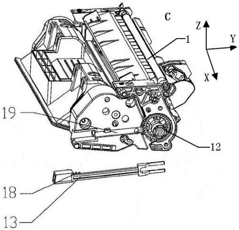
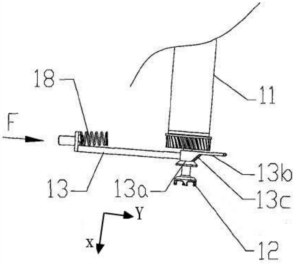
[0033] The power transmission device of the present invention is installed at one end of the photosensitive element, the photosensitive element also includes a photosensitive cylinder, the power transmission device is installed at the end of the photosensitive cylinder, and the power transmission device is used to transmit the received driving force to the photosensitive cylinder and is used to drive the rotation of the entire photosensitive element.

[0034] The present invention also relates to a process cartridge, which includes a photosensitive element rotatably installed therein. The photosensitive element receives driving force to rotate through a power transmission device, and completes an imaging process together with other components in the process cartridge.

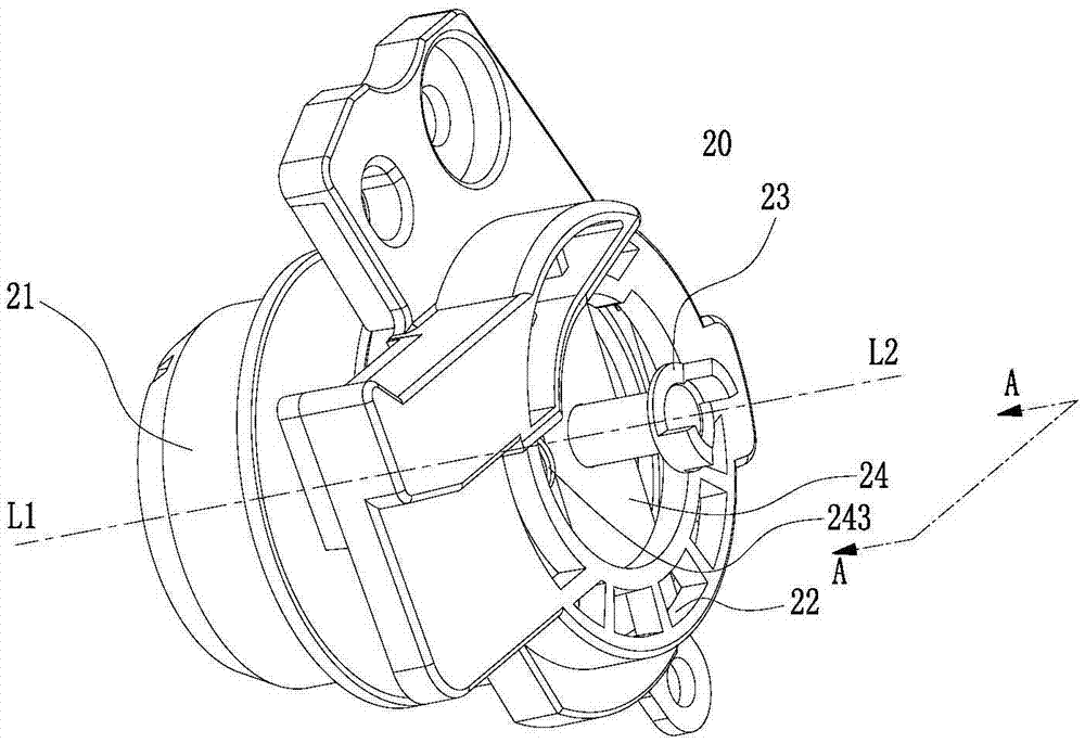
[0035] [Structure of power transmission devic...


PUM


Abstract

The invention relates to a power transfer device, and a photosensitive element and processing cartridge having the power transfer device. The power transfer device comprises a flange having a rotation axis L1, a flange bracket, a power receiving part and a power transfer part mounted in the flange, and a moving part, wherein the flange bracket is used for supporting the flange; the power transfer part is mounted in the power receiving part; the power receiving part is penetrated through the moving part; and the moving part is mounted between the flange and the flange bracket. When the power transfer device and a power output device are connected or disconnected, the acting force of a printer door is not needed, thereby effectively ensuring that the photosensitive element or processing cartridge provided with the power transfer device can be widely used.

Description

technical field [0001] The invention relates to the field of electrophotographic imaging, in particular to a power transmission device, a photosensitive element and a process box with the power transmission device. Background technique [0002] A printer is a type of electrophotographic imaging device, and a process cartridge detachably installed in the printer is a consumable therein. The process cartridge works by receiving driving force from the printer. In order to obtain the driving force required for the process cartridge to work, Generally, a power output device is arranged in the printer, and a power transmission device is arranged in the process box. After the process box is loaded into the printer, the power transmission device is combined with the power output device to receive and transmit driving force; When it is disassembled, the power transmission device is disengaged from the power output device. [0003] figure 1 is a schematic diagram of the overall stru...

Claims


Application Information

Patent Timeline
Patent Type & Authority Applications(China)
IPC IPC(8): G03G21/18
CPCG03G21/1857
Inventor 刘均庆
Owner ZHONGSHAN KINGWAY IMAGE TECH CO LTD
Why Eureka
Try Eureka