
Sonar technology-based oily deposit automatic identification method and system

An automatic identification system and automatic identification technology, applied in character and pattern recognition, instruments, computer parts, etc., can solve the problems of inconvenient use, weak acoustic impedance characteristics, pipeline leakage, etc., and achieve broad application prospects and accurate identification. and forecast, achieve simple effects

Inactive Publication Date: 2017-06-27
中海石油环保服务(天津)有限公司
View PDF5 Cites 4 Cited by
  • Summary
  • Abstract
  • Description
  • Claims
  • Application Information

AI Technical Summary

Problems solved by technology

[0002] With the continuous development of the exploration and development of offshore oil and gas resources, the laying range of oil pipelines on the seabed, which is the "lifeline" of offshore oil transportation, is increasing. During the use of oil pipelines, due to equipment aging, seawater corrosion, waves and tides The impact of hydrodynamic effects, such as oil spills caused by pipeline leakage, perforation and rupture, have brought huge challenges to the safety of the marine environment
Oil-bearing sediments have the characteristics of "weak acoustic impedance characteristics and no obvious shadow areas". The laying of submarine oil pipelines requires a certain burial depth, and inspection and maintenance are difficult. Crude oil leaking from oil pipelines produces continuous diffusion of point sources. The leakage is mixed with sediments such as seabed mud and sand in the early stage, and gradually diffuses to the sea surface in the later stage. The existing technology cannot effectively realize automatic, rapid and accurate identification and detection of oily sediments, so it is extremely inconvenient to use

Method used


Image

  • Sonar technology-based oily deposit automatic identification method and system
  • Sonar technology-based oily deposit automatic identification method and system
  • Sonar technology-based oily deposit automatic identification method and system

Examples


Embodiment Construction

[0012] Certain terms are used, for example, in the description and claims to refer to particular components. Those skilled in the art should understand that hardware manufacturers may use different terms to refer to the same component. The specification and claims do not use the difference in name as a way to distinguish components, but use the difference in function of components as a criterion for distinguishing. As mentioned throughout the specification and claims, "comprising" is an open term, so it should be interpreted as "including but not limited to". "Approximately" means that within an acceptable error range, those skilled in the art can solve the technical problem within a certain error range and basically achieve the technical effect. The subsequent description of the specification is a preferred implementation mode for implementing the application, but the description is for the purpose of illustrating the general principle of the application, and is not intended...


PUM


Abstract

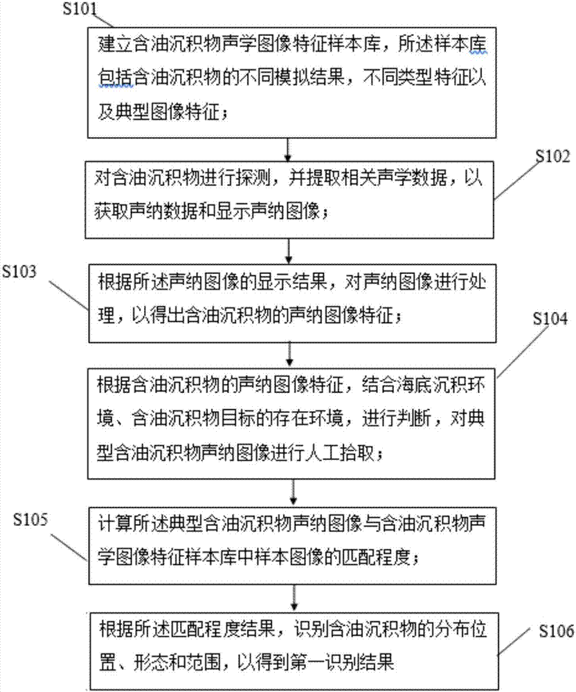
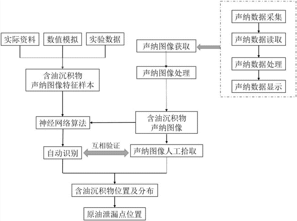
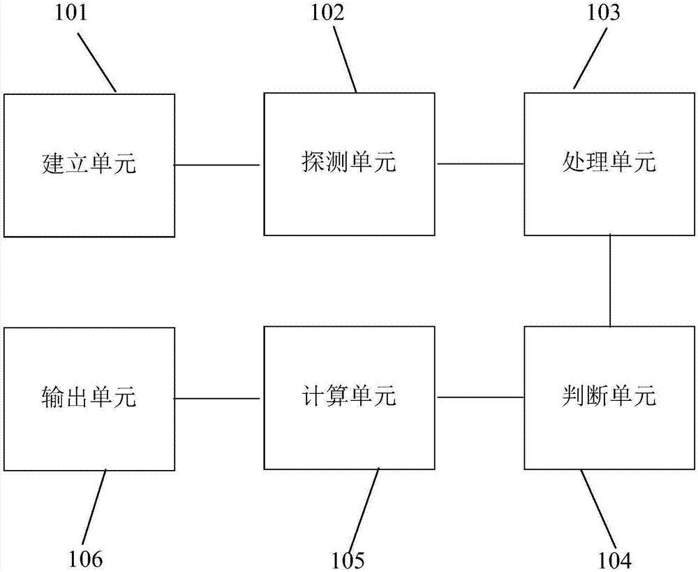
The invention discloses a sonar technology-based oily deposit automatic identification method and system. The method comprises the steps of establishing an oily deposit acoustic image feature sample library, wherein the sample library comprises different simulation results, different type features and typical image features of an oily deposit; detecting the oily deposit, extracting related acoustic data to obtain sonar data, and displaying a sonar image; according to a display result of the sonar image, processing the sonar image to obtain sonar image features of the oily deposit; according to the sonar image features of the oily deposit, in combination with a sea-bottom deposit environment and an environment in which an oily deposit target exists, performing judgment, and performing manual pickup on a typical oily deposit sonar image; calculating a matching degree between the typical oily deposit sonar image and a sample image in the oily deposit acoustic image feature sample library; and according to a matching degree result, identifying the distribution position, shape and range of the oily deposit to obtain a first identification result. The method and the system have the advantages of quick identification, convenient use and accurate identification of the oily deposit.

Description

technical field [0001] The invention belongs to the technical field of marine environment protection and relates to an automatic identification method for oily deposits based on sonar technology. Background technique [0002] With the continuous development of the exploration and development of offshore oil and gas resources, the laying range of oil pipelines on the seabed, which is the "lifeline" of offshore oil transportation, is increasing. During the use of oil pipelines, due to equipment aging, seawater corrosion, waves and tides The impact of hydrodynamic effects, such as oil leakage caused by pipeline leakage, perforation and rupture, has brought huge challenges to the safety of the marine environment. Oil-bearing sediments have the characteristics of "weak acoustic impedance characteristics and no obvious shadow areas". The laying of submarine oil pipelines requires a certain burial depth, and inspection and maintenance are difficult. Crude oil leaking from oil pipel...

Claims


Application Information

Patent Timeline
Patent Type & Authority Applications(China)
IPC IPC(8): G06K9/00
CPCG06F2218/08G06F2218/12
Inventor 栗宝鹃安伟赵宇鹏靳卫卫李建伟刘保占张庆范赵建平
Owner 中海石油环保服务(天津)有限公司
Learn More