Rust removal preparation device for LED (light-emitting diode) lamp holder manufacture

A technology of LED lamp holders and equipment, which is applied in the direction of mixer accessories, dissolving machines, mixers, etc., can solve the problems of inability to collect rust removers, inability to prepare multi-stage stirring, etc., and achieve the effect of full mixing

Inactive Publication Date: 2017-06-30
宁波伍兹光电有限公司
View PDF2 Cites 20 Cited by
  • Summary
  • Abstract
  • Description
  • Claims
  • Application Information

AI Technical Summary

Problems solved by technology

[0006] In order to overcome the shortcomings in the prior art that multi-stage stirring preparation cannot be performed and the rust remover cannot be collected after the rust removal is completed, the technical problem to be solved by the present invention is to provide a multi-stage stirring preparation , and the preparation equipment that can collect the rust remover after the rust removal is completed

Method used


Image

  • Rust removal preparation device for LED (light-emitting diode) lamp holder manufacture
  • Rust removal preparation device for LED (light-emitting diode) lamp holder manufacture
  • Rust removal preparation device for LED (light-emitting diode) lamp holder manufacture

Examples


Embodiment 1

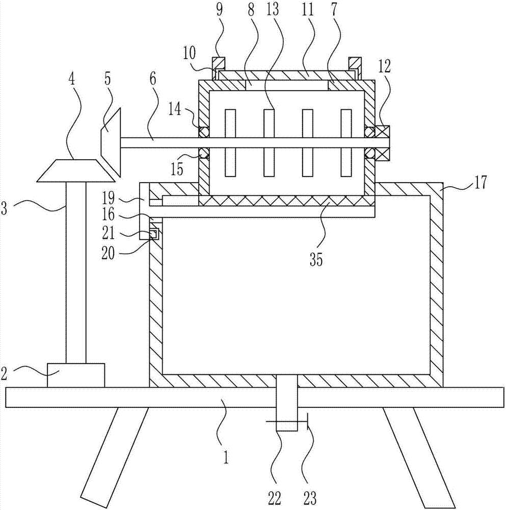
[0029] A kind of derusting preparation equipment for LED lamp holder production, such as Figure 1-4As shown, it includes a workbench 1, a motor 2, a first rotating rod 3, a first bevel gear 4, a second bevel gear 5, a second rotating rod 6, a mixing box 7, a pole 9, a baffle plate 11, a first Bearing seat 12, first stirring rod 13, sealing ring 15, storage box 17, pull rod 19, rubber block 21, discharge pipe 22, valve 23 and filter screen 35, motor 2 and motor 2 are installed on the left side of the top of workbench 1 The first rotary rod 3 is connected to the output shaft of the first rotary rod 3, the first bevel gear 4 is connected to the top of the first rotary rod 3, the storage box 17 is connected to the right side of the top of the workbench 1, and the bottom center of the storage box 17 is connected to the discharge pipe 22. The discharge pipe 22 is provided with a valve 23, and the upper part of the left wall of the storage box 17 has a second small hole 16, and the ...

Embodiment 2

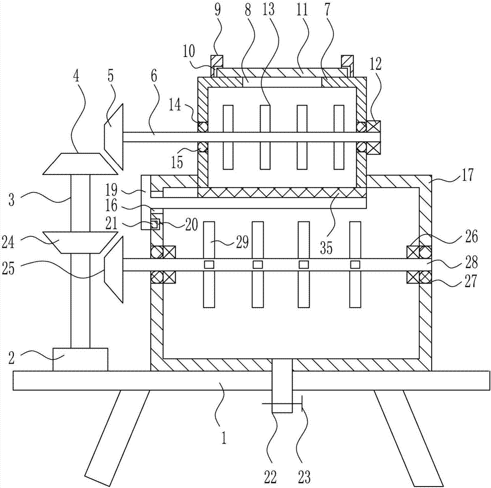
[0031] A kind of derusting preparation equipment for LED lamp holder production, such as Figure 1-4 As shown, it includes a workbench 1, a motor 2, a first rotating rod 3, a first bevel gear 4, a second bevel gear 5, a second rotating rod 6, a mixing box 7, a pole 9, a baffle plate 11, a first Bearing seat 12, first stirring rod 13, sealing ring 15, storage box 17, pull rod 19, rubber block 21, discharge pipe 22, valve 23 and filter screen 35, motor 2 and motor 2 are installed on the left side of the top of workbench 1 The first rotary rod 3 is connected to the output shaft of the first rotary rod 3, the first bevel gear 4 is connected to the top of the first rotary rod 3, the storage box 17 is connected to the right side of the top of the workbench 1, and the bottom center of the storage box 17 is connected to the discharge pipe 22. The discharge pipe 22 is provided with a valve 23, and the upper part of the left wall of the storage box 17 has a second small hole 16, and the...

Embodiment 3

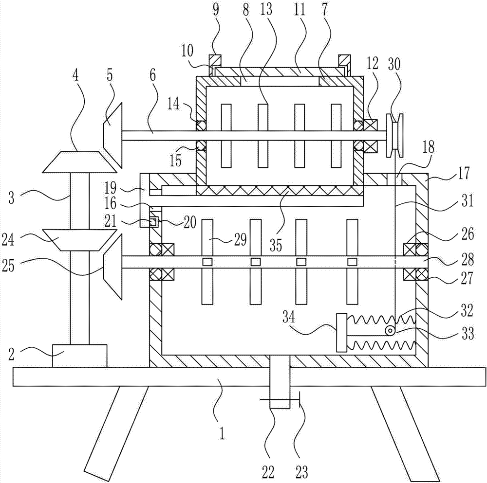
[0034] A kind of derusting preparation equipment for LED lamp holder production, such as Figure 1-4 As shown, it includes a workbench 1, a motor 2, a first rotating rod 3, a first bevel gear 4, a second bevel gear 5, a second rotating rod 6, a mixing box 7, a pole 9, a baffle plate 11, a first Bearing seat 12, first stirring rod 13, sealing ring 15, storage box 17, pull rod 19, rubber block 21, discharge pipe 22, valve 23 and filter screen 35, motor 2 and motor 2 are installed on the left side of the top of workbench 1 The first rotary rod 3 is connected to the output shaft of the first rotary rod 3, the first bevel gear 4 is connected to the top of the first rotary rod 3, the storage box 17 is connected to the right side of the top of the workbench 1, and the bottom center of the storage box 17 is connected to the discharge pipe 22. The discharge pipe 22 is provided with a valve 23, and the upper part of the left wall of the storage box 17 has a second small hole 16, and the...


PUM


Abstract

The invention relates to a rust removal preparation device, in particular to a rust removal preparation device for LED (light-emitting diode) lamp holder manufacture, and aims to provide a preparation device which can achieve multistage stirring preparation and collect rust removers after rust removal. The rust removal preparation device comprises a working table, a motor, a first rotating rod, a first bevel gear, a second bevel gear, a second rotating rod, a stirring box, a supporting rod, a baffle plate, a first bearing block, a first stirring rod and the like, wherein the motor is mounted on the left side of the top of the working table, the first rotating rod is connected to the output shaft of the motor, and the first bevel gear is connected to the top end of the first rotating rod. The rust removal preparation device is further provided with a third bevel gear, a fourth bevel gear, a second bearing block, a fourth rotating rod and a second stirring rod.

Description

technical field [0001] The invention relates to a derusting compounding device, in particular to a derusting compounding device for manufacturing LED lamp holders. Background technique [0002] LED: Its basic structure is an electroluminescent semiconductor material chip, which is cured on the bracket with silver glue or white glue, and then connected to the chip and circuit board with silver or gold wires, and then sealed with epoxy resin around it to play a role. The role of protecting the inner core wire, and finally install the shell, so its shock resistance is good. The field of application involves mobile phones, table lamps, home appliances and other daily household appliances and machinery production. The LED lamp holder is a transparent lampshade made of imported polycarbonate injection molding. It has high strength and good light transmission. It uses LED light source. [0003] In the existing manufacturing process of LED lamp holders, derusting the LED lamp hold...

Claims


Application Information

Patent Timeline
Patent Type & Authority Applications(China)
IPC IPC(8): B01F13/10
CPCB01F33/811B01F35/188B01F2101/4505
Inventor 张晓艳
Owner 宁波伍兹光电有限公司
Why Eureka
Try Eureka