Stainless steel circular thin plate origin forming mechanism

A molding mechanism, stainless steel technology, applied in the direction of molding tools, metal processing equipment, manufacturing tools, etc., can solve the problems of upper mold and lower mold damage, easy adhesion to the lower mold, troublesome demoulding, etc., to achieve fast demoulding, Effect of reducing hard impact and improving service life

Active Publication Date: 2017-06-30
江门市德高实业有限公司
View PDF6 Cites 13 Cited by
  • Summary
  • Abstract
  • Description
  • Claims
  • Application Information

AI Technical Summary

Problems solved by technology

[0004] In the existing stainless steel circular thin plate stamping mechanism, the upper mold and the lower mold both adopt a fixed connection structure. During stamping, hard collisions are likely to occur, and the upper mold and the lower mold are easily damaged.
[0005] At the same time, the existing stainless steel circular thin plate is easy to adhere to the lower mold after stamping and forming, and it is troublesome to demould

Method used


Image

  • Stainless steel circular thin plate origin forming mechanism
  • Stainless steel circular thin plate origin forming mechanism

Examples


Embodiment Construction

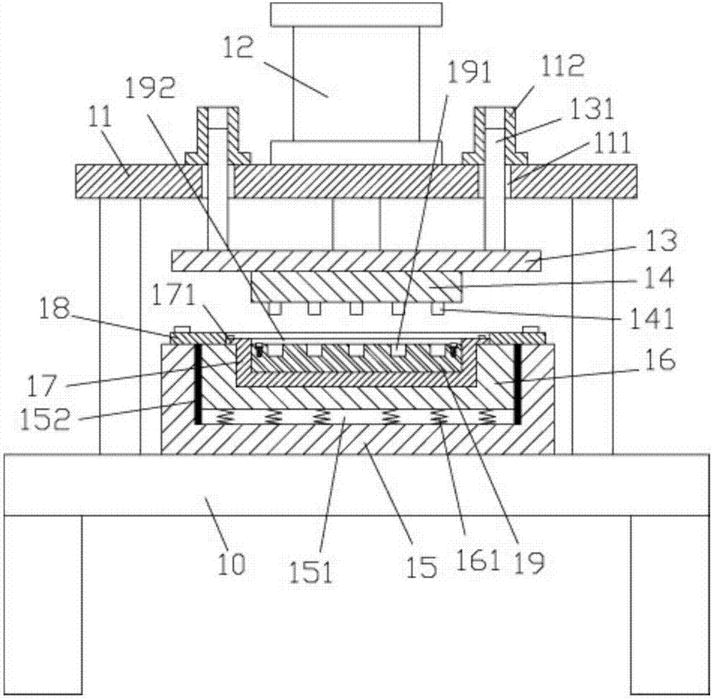
[0021] Examples, see as Figure 1 to Figure 2 As shown, a stainless steel circular sheet origin forming mechanism includes a frame 10, an upper support frame 11 is fixed on the top surface of the top plate of the frame 10, and a stamping cylinder 12 is fixed in the middle of the top surface of the top plate of the upper support frame 11. , the push rod of the punching cylinder 12 passes through the top plate of the upper support frame 11 and is fixed with the upper connecting plate 13, the middle of the bottom surface of the upper connecting plate 13 is fixed with the upper die 14, and the bottom surface of the upper die 14 is evenly distributed with a plurality of punching bumps 141 ;

[0022] The lower support block 15 is fixed on the top surface of the middle part of the top plate of the rack 10 , the middle part of the top surface of the lower support block 15 has a main groove 151 , the installation block 16 is inserted into the main groove 151 , and the bottom surface of...


PUM


Abstract

The invention discloses a stainless steel circular thin plate origin forming machine. The stainless steel circular thin plate origin forming machine comprises a rack, wherein an upper supporting frame is fixedly arranged on the top surface of a top plate of the rack; a stamping oil cylinder is fixedly arranged on the middle part of the top surface of the top plate of the upper supporting frame; a pushing rod of the stamping oil cylinder passes through the top plate of the upper supporting frame and is fixedly equipped with an upper supporting plate; an upper mould is fixedly arranged on the middle of the bottom surface of the upper connecting plate; a plurality of stamping convex points are uniformly distributed on the bottom surface of the upper mould; the top surface of the middle part of the top plate of the rack is fixedly equipped with a lower supporting block; a main groove is formed in the middle part of the top surface of the lower supporting block; a mounting block is in plug bush in the main groove; a plurality of buffer springs are fixedly arranged on the bottom surface of the mounting block; the lower ends of the buffer springs are fixedly arranged on the bottom surface of the main groove; and an upper ring-shaped plate is fixedly connected to the top surfaces of the lower supporting blocks through bolts, and resists against the side part of the top surface of the mounting block. According to the stainless steel circular thin plate origin forming machine disclosed by the invention, hard collision between an upper mould and a lower mould can be reduced, so that the stainless steel circular thin plate origin forming machine is prevented from being damaged, and the service life of the stainless steel circular thin plate origin forming machine is prolonged; and meanwhile, the stainless steel circular thin plate origin forming machine is not easily adhered on the lower mould, and is quick in de-molding.

Description

[0001] Technical field: [0002] The invention relates to the technical field of stainless steel product processing, and more particularly to a stainless steel circular sheet origin forming mechanism. [0003] Background technique: [0004] In the existing stainless steel circular thin plate punching mechanism, the upper die and the lower die are both fixed and connected, and hard collision is likely to occur during punching, and the upper die and the lower die are easily damaged. [0005] At the same time, the existing round stainless steel sheet is easy to adhere to the lower mold after stamping and forming, and it is troublesome to demold. [0006] Invention content: [0007] The purpose of the present invention is to overcome the deficiencies of the prior art and provide a stainless steel circular thin plate origin forming mechanism, which can reduce the hard collision between the upper mold and the lower mold, reduce its damage, and improve the service life, and at the sa...

Claims


Application Information

Patent Timeline
Patent Type & Authority Applications(China)
IPC IPC(8): B21D37/10B21D45/04
CPCB21D37/10B21D45/04
Inventor 陈玉燕
Owner 江门市德高实业有限公司
Why Eureka
Try Eureka