
Double-face chamfering and drilling tool

A drilling tool, double-sided technology, used in drilling tool accessories, drilling/drilling equipment, drilling and other directions, can solve the problems that the surface quality cannot meet high-quality products, affect the quality of the processed surface, and the processing efficiency is not high. Achieve the effect of ensuring cutting performance and processing quality, saving processing time and worker operation time, and good processing quality

Inactive Publication Date: 2017-06-30
四川天虎工具有限责任公司
View PDF8 Cites 7 Cited by
  • Summary
  • Abstract
  • Description
  • Claims
  • Application Information

AI Technical Summary

Problems solved by technology

The first processing method has the problems of tool change and secondary clamping, which not only has low production efficiency, but also easily causes chamfering and drilling without concentricity, and the rate of defective products is high; the second processing method uses a portable chamfering machine for chamfering. The surface quality cannot meet the requirements of high-quality products; the third processing method requires CNC machine tools to chamfer the holes at both ends by interpolation milling. The processing efficiency is not high, and the tool rigidity is poor, which affects the processing surface. quality
Especially when the chamfering accuracy and efficiency are high, none of the above three processing methods can better meet these two requirements at the same time

Method used


Image

  • Double-face chamfering and drilling tool
  • Double-face chamfering and drilling tool
  • Double-face chamfering and drilling tool

Examples


Embodiment Construction

[0018] The present invention will be further described below in conjunction with the accompanying drawings, but the protection scope of the present invention is not limited to the following description.

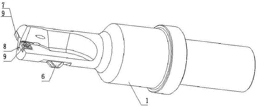
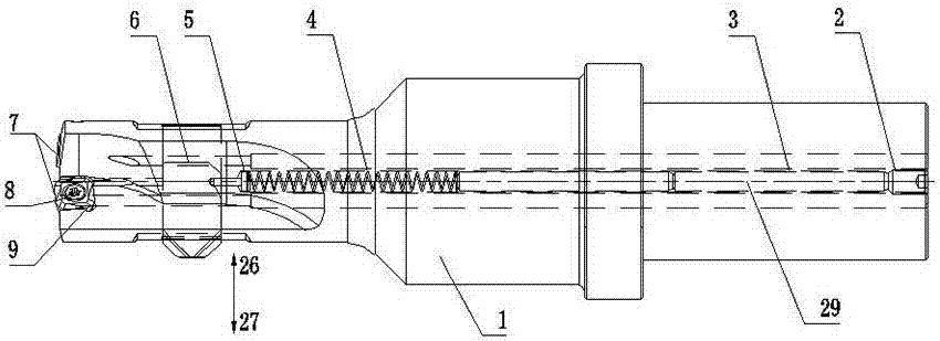
[0019] Such as Figure 1~Figure 5 As shown, a double-sided chamfering drilling tool includes a cutter body 1, a chamfering blade 6 and a drilling blade 7, the end of the cutter body 1 is provided with a blade platform 9, and the end of the cutter body 1 The head is also provided with a longitudinally arranged blade installation transverse hole 19, the right end of the cutter body 1 is provided with a clamping portion 28, the inside of the cutter body 1 is provided with an axial hole 20, and one end of the extension rod 3 is positioned and fixed by the set screw 2. Installed in the axial hole 20, the other end of the extension rod 3 is connected with a spring 4, and the spring 4 is connected with the limit pin 5; the drilling blade 7 is installed on the blade platform 9 throug...


PUM


Abstract

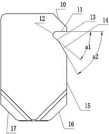
The invention discloses a double-sided chamfering drilling tool, which comprises a cutter body, a chamfering blade and a drilling blade, the end of the cutter body is provided with a blade platform, and the end of the cutter body is provided with a blade Install the horizontal hole, the right end of the cutter body is provided with a clamping part, the inside of the cutter body is provided with an axial hole, one end of the extension rod is positioned and installed in the axial hole by a set screw, and the other end of the extension rod is connected with a spring , the spring is connected with the limit pin; the drilling blade is mounted on the blade platform through a compression screw; a groove is provided in the longitudinal direction of the chamfering blade, and the lower end side wall of the groove is a first inclined plane The chamfering insert has a front chamfering edge and a reverse chamfering edge on the cutting surface. The chamfering insert is installed in the horizontal hole of the insert, and the limit pin is inserted into the groove to lock the chamfering insert. Lock and limit. The beneficial effects of the invention are: convenient processing, double-sided chamfering processing, high processing efficiency and good processing quality.

Description

technical field [0001] The invention relates to the technical field of structural design of metal cutting tools, in particular to a double-sided chamfering drilling tool. Background technique [0002] In the processing of mechanical parts, hole machining generally requires hole chamfering. At present, there are three main processing methods: the first is to drill the hole first, and then change the chamfering knife to chamfer the holes at both ends; the second is to drill After the hole is made, use a portable chamfering knife machine to chamfer the holes at both ends; the third is to use the two fixed blades at the rear end to interpolate and mill the holes at both ends after drilling. The first processing method has the problems of tool change and secondary clamping, which not only has low production efficiency, but also easily causes chamfering and drilling without concentricity, and the rate of defective products is high; the second processing method uses a portable ch...

Claims


Application Information

Patent Timeline
IPC IPC(8): B23B51/08
CPCB23B51/08
Inventor 梁元杰赵彩云赵骏龚健蒋文云
Owner 四川天虎工具有限责任公司
Learn More