
Machining method for ductile iron crankshaft thrust surfaces

A processing method and thrust surface technology, applied in the direction of the crankshaft, can solve the problems of grinding burn equipment, expensive, etc., and achieve the effect of solving the burn problem

Inactive Publication Date: 2017-06-30
JIANGLING MOTORS
View PDF3 Cites 1 Cited by
  • Summary
  • Abstract
  • Description
  • Claims
  • Application Information

AI Technical Summary

Problems solved by technology

For this reason, the purpose of the present invention is to propose a processing method for the thrust surface of a nodular iron crankshaft, which solves the problem of grinding burns produced by the grinding process and expensive equipment in the finish car rolling process when the thrust surface of the nodular iron crankshaft is processed

Method used


Image

  • Machining method for ductile iron crankshaft thrust surfaces
  • Machining method for ductile iron crankshaft thrust surfaces
  • Machining method for ductile iron crankshaft thrust surfaces

Examples


Embodiment Construction

[0036] Embodiments of the present invention are described in detail below, examples of which are shown in the drawings, wherein the same or similar reference numerals designate the same or similar elements or elements having the same or similar functions throughout. The embodiments described below by referring to the figures are exemplary only for explaining the present invention and should not be construed as limiting the present invention.

[0037] These and other aspects of embodiments of the invention will become apparent with reference to the following description and drawings. In these descriptions and drawings, some specific implementations of the embodiments of the present invention are specifically disclosed to represent some ways of implementing the principles of the embodiments of the present invention, but it should be understood that the scope of the embodiments of the present invention is not limited by this limit. On the contrary, the embodiments of the present...


PUM


Abstract

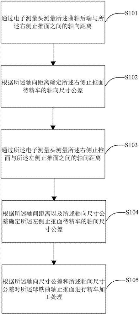
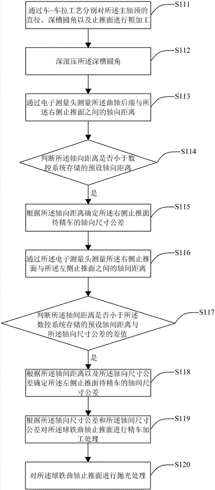
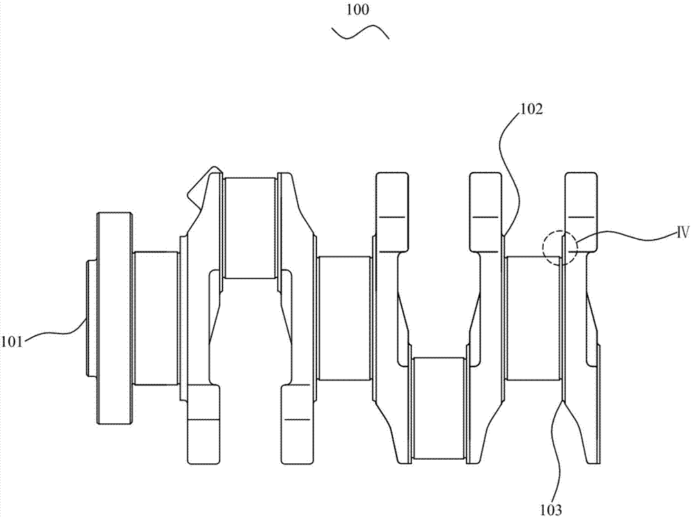
The invention discloses a machining method for ductile iron crankshaft thrust surfaces. A crankshaft comprises a crankshaft back end and main journals, and the thrust surfaces of each main journal comprise a left-side thrust surface and a right-side thrust surface which are arranged oppositely. The method comprises the steps as follows: the axial distances between the crankshaft back end and the right-side thrust surfaces as well as the inter-axis distances between the right-side thrust surfaces and the left-side thrust surfaces are measured by an electronic measuring head; to-be-finish-turned axial dimension tolerance of the right-side thrust surfaces is determined according to the axial distances; the to-be-finish-turned inter-axis dimension tolerance of the left-side thrust surfaces is determined according to the inter-axis distances and the axial dimension tolerance; and finish-turning machining is performed on the crankshaft thrust surfaces according to the axial dimension tolerance and the inter-axis dimension tolerance. According to the machining method for the ductile iron crankshaft thrust surfaces, the axial distances and the inter-axis distances are measured by the electronic measuring head, the to-be-finish-turned machining allowance of the thrust surfaces is determined, finish-turning is performed, the problem of grinding burning caused by grinding machining of the thrust surfaces is solved with the finish-turning technology, and the equipment investment cost is less than that of the finish-turning and rolling technology.

Description

technical field [0001] The invention relates to the technical field of mechanical equipment processing, in particular to a processing method for a nodular iron crankshaft thrust surface. Background technique [0002] The crankshaft is one of the most important and heavily loaded components in a piston engine. The crankshaft, connecting rods, and pistons together form a crank-connecting rod mechanism. When the engine is working, the downward thrust of the piston is transmitted to the crankshaft through the connecting rod, and the reciprocating motion of the piston is converted into the rotary motion of the crankshaft through the crankshaft, and mechanical work is output, and the car is driven through the transmission mechanism of the car chassis, while the thrust surface of the crankshaft is The benchmark for subsequent finishing of the crankshaft, so the processing quality of the thrust surface of the crankshaft directly affects the quality of other processes. [0003] The ...

Claims


Application Information

Patent Timeline
Patent Type & Authority Applications(China)
IPC IPC(8): B23P15/14
CPCB23P15/14F16C3/06
Inventor 陈剑峰刘南平章见义黎维俊江华星邓峰邱焕华
Owner JIANGLING MOTORS
Learn More