Ultrahigh-pressure fully-automatic pressure relief device

A pressure relief device, fully automatic technology, applied in the direction of fluid pressure actuating device, servo motor components, mechanical equipment, etc., can solve the problems of inability to achieve linear changes in system pressure, low pressure relief accuracy, and poor distance control. The effect of avoiding long-term pressure, smooth pressure relief, and improving service life

Active Publication Date: 2017-06-30
ZHENGZHOU SINO CRYSTAL DIAMOND
View PDF7 Cites 2 Cited by
  • Summary
  • Abstract
  • Description
  • Claims
  • Application Information

AI Technical Summary

Problems solved by technology

[0002] The pressure required by the ultra-high pressure hydraulic system of the existing six-sided top press is generally between 80 and 120 MPa when synthesizing superhard materials. When synthesizing superhard materials, a linearly changing and stable system pressure is required; China with application number 201410635210.8 The patent discloses a gap-type ultra-high pressure pressure relief valve. The pressure relief speed of the pressure relief valve changes in jumps, and the linear change of the system pressure cannot be realized; the Chinese patent application number 201610666876.9 discloses a stepless variable ultra-high pressure pressure relief valve. Servo pressure relief valve, the pressure relief valve uses a servo motor to provide a stable system pressure, but the distance between the screw and the valve stem is not easy to control, resulting in low pressure relief accuracy

Method used


Image

  • Ultrahigh-pressure fully-automatic pressure relief device
  • Ultrahigh-pressure fully-automatic pressure relief device
  • Ultrahigh-pressure fully-automatic pressure relief device

Examples


Embodiment 1

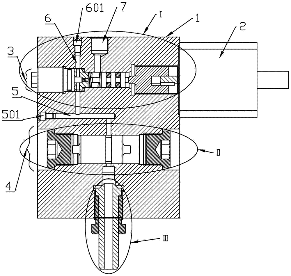
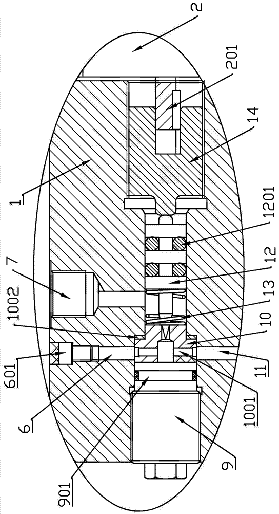
[0030] Embodiment one, such as Figure 1-3 , 6, 7 An ultra-high pressure automatic pressure relief device, including a main body 1 and a stepper motor 2 located on the right side of the main body 1, the main body 1 includes a pressure relief chamber 3 transparent on both sides, and the pressure relief chamber 3 Including the blocking cavity on the left, the regulating cavity on the middle and the threaded cavity on the right;

[0031] The plug I9 on the left side and the valve seat 10 on the right side are provided in the plugging cavity, the valve seat 10 is provided with a cross-shaped valve port 1001, and the top and bottom of the plugging cavity are respectively provided with The safety hole 6 and the first oil inlet hole 11, the safety hole 6 and the first oil inlet hole 11 are both connected to the valve port 1001, and the outlet of the safety hole 6 is provided with a safety valve I501;

[0032] There is a thimble 12 which is thinner on the left and thicker on the righ...

Embodiment 2

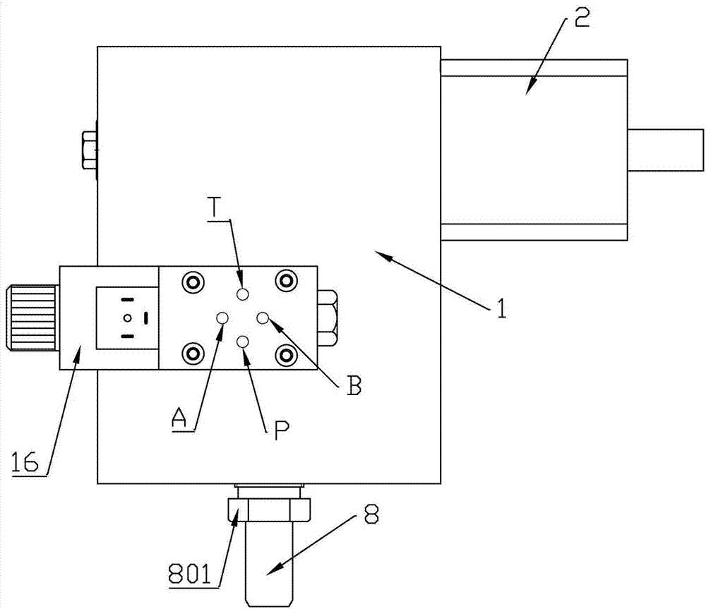
[0048] Embodiment two, such as Figure 1-7, basically the same as Embodiment 1, the difference is that it also includes a solenoid valve 16 installed on the main body 1, the solenoid valve 16 is a two-position four-way hydraulic solenoid valve 16, and the solenoid valve 16 is provided with an A port , B port, P port and T port, the main body 1 also includes a pressure-holding chamber 4 transparent at both ends, the two ends of the pressure-holding chamber 4 are blocked with screw plugs II15, and the spool of the solenoid valve 16 1601 is located in the pressure-holding chamber 4, the A port communicates with the left side of the pressure-holding chamber 4, the B oral language communicates with the right side of the pressure-holding chamber 4, the P port communicates with the hydraulic pump, and the T port communicates with the return The oil tank is connected, the valve core 1601 is provided with an annular groove 1602 close to the right end, and the second oil inlet hole 18 o...

Embodiment 3

[0049] Embodiment three, such as Figure 1-5 , is basically the same as Embodiment 1 or Embodiment 2. Preferably, the right side of the screw plug I9 is ​​provided with a seal groove I901 for installing a gasket, and the right half of the thimble 12 is provided with at least two seal grooves for installing a gasket. Sealing groove II 1201, the right side of the valve seat 10 is provided with a copper gasket 1002 located at the rightmost end of the sealing cavity.


PUM


Abstract

The invention discloses an ultrahigh-pressure fully-automatic pressure relief device. The ultrahigh-pressure fully-automatic pressure relief device comprises a main body and a step motor positioned at the right side of the main body, wherein the main body comprises a pressure relief cavity which is through in two sides; the pressure relief cavity comprises a sealing cavity at the left side, a regulating cavity on the middle and a threaded cavity at the right side, wherein a screw plug I at the left side and a valve seat at the right side are arranged in the sealing cavity; an ejector pin which is thin in left portion and thick in right portion is arranged in the regulating cavity; the left end of the ejector pin is equipped with a tip which extends into a valve hole; the threaded cavity is internally matched with a screw; the left end of the screw is bumped, and abuts against the right end of the ejector pin; the right end of the screw is equipped with a shaft hole with a key slot; the shaft hole is in clearance fit with a motor shaft of the step motor through a flat key; the lower end of the main body is equipped with an oil inlet which is fixedly equipped with an oil inlet nozzle; and the oil inlet communicates with a first oil inlet hole path. According to the ultrahigh-pressure fully-automatic pressure relief device disclosed by the invention, the step motor is adopted to drive the screw to regulate movement of the ejector pin, so that the tip is regulated to extend into the valve opening by certain length, and therefore, linear pressure relief is realized, linear changes of system pressure are realized, and a production process curve is met.

Description

technical field [0001] The invention relates to the technical field of automatic adjustment and pressure relief of a hydraulic system, in particular to an ultra-high pressure full-automatic pressure relief device. Background technique [0002] The pressure required by the ultra-high pressure hydraulic system of the existing six-sided top press is generally between 80 and 120 MPa when synthesizing superhard materials. When synthesizing superhard materials, a linearly changing and stable system pressure is required; China with application number 201410635210.8 The patent discloses a gap-type ultra-high pressure pressure relief valve. The pressure relief speed of the pressure relief valve changes in jumps, and the linear change of the system pressure cannot be realized; the Chinese patent application number 201610666876.9 discloses a stepless variable ultra-high pressure pressure relief valve. Servo pressure relief valve, the pressure relief valve uses a servo motor to basicall...

Claims


Application Information

Patent Timeline
Patent Type & Authority Applications(China)
IPC IPC(8): F15B13/02
CPCF15B13/024
Inventor 刘创勋刘永奇姜豪李烨穆小娜
Owner ZHENGZHOU SINO CRYSTAL DIAMOND
Why Eureka
Try Eureka