
Light-controlled LED light supplement lamp

An LED fill light and LED light technology, applied in the field of lighting, can solve the problems of long-term lighting power control and heat dissipation, which limit wide application, it is difficult to achieve a 3-year life, and reduce the life of the fill light, etc., to achieve the light control effect. Better and more reasonable, longer life, and more reasonable structure

Inactive Publication Date: 2017-06-30
WEIHAI PUBLIC SECURITY BUREAU WENDENG BRANCH
View PDF6 Cites 2 Cited by
  • Summary
  • Abstract
  • Description
  • Claims
  • Application Information

AI Technical Summary

Problems solved by technology

In terms of traffic LED fill light, it can be divided into continuous light and strobe light in terms of light emitting mode. Among them, the long light has good stability, the fill light effect is stable, and it is not easy to be disturbed by the outside world. However, the power control of the long light and heat dissipation problems largely limit its wide application
Under the condition of working outdoors, the LED fill light is required to have a sealing function due to the influence of snow, rain, wind and sand. In addition, the long-term work produces a lot of heat and the heat dissipation effect is not ideal, which greatly reduces the life of the fill light. Difficult to meet the 3-year lifespan requirement
[0004] How to adopt a design with a small amount of construction and a simple connection method can not only ensure the sealing of the LED fill light and the stability of the luminous effect, but also improve the heat dissipation of the fill light and prolong its life, which has always been a difficult problem in the lighting industry. There have been no successful cases at home and abroad so far. With the economic and social development and the need to combat crimes, this demand is more urgent

Method used


Image

  • Light-controlled LED light supplement lamp
  • Light-controlled LED light supplement lamp
  • Light-controlled LED light supplement lamp

Examples


Embodiment Construction

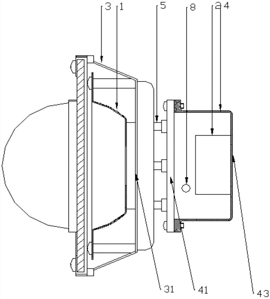
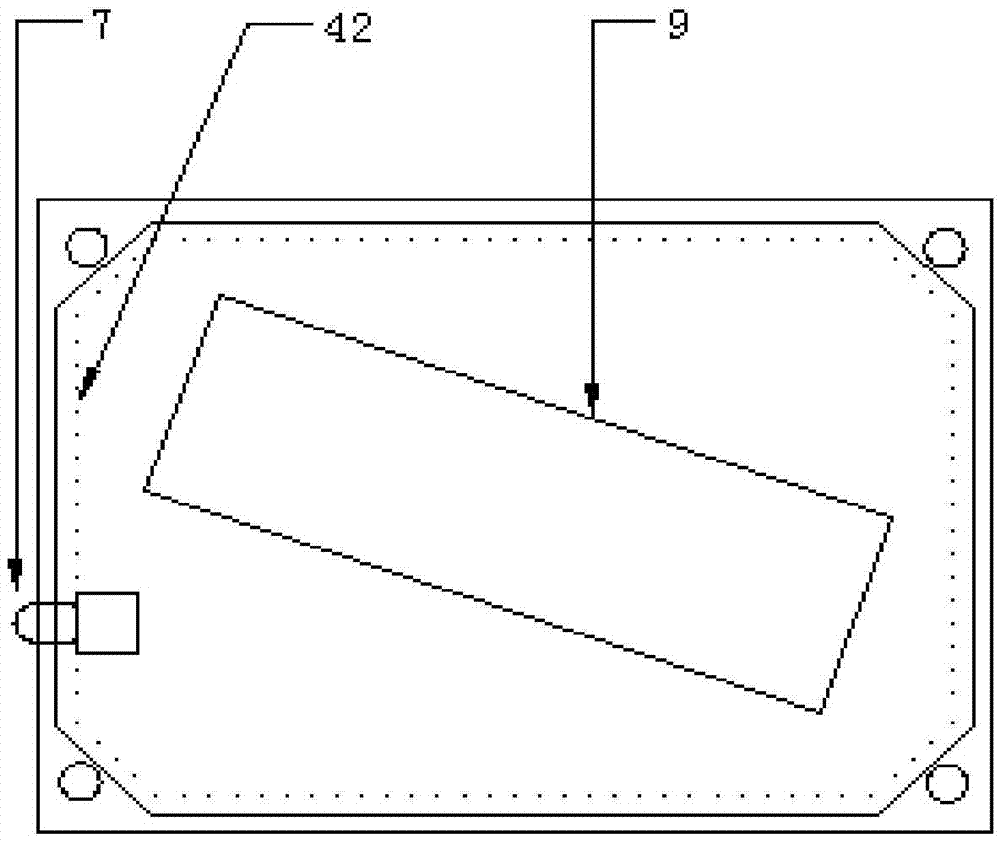
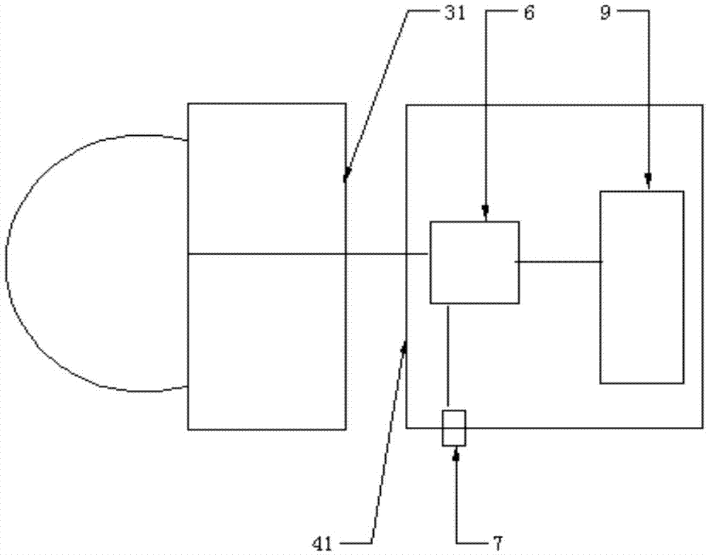
[0028] Such as figure 1 As shown, a light-controlled LED supplementary light of the present invention includes an LED lamp 1 and a circuit control module 2, which are respectively packaged in a front casing 3 and a rear casing 4, and the rear wall 31 of the front casing and the rear wall of the rear casing The front wall 41 is connected through the support rod 5; the circuit control module 2 includes a light control circuit board 6 and a photodiode 7, the light control circuit board 6 is electrically connected to the LED lamp 1, and the photodiode 7 is electrically connected to the light control circuit board 6. Such as figure 2 As shown, the photosensitive diode 7 is embedded on the outer wall 42 of the rear case, and the top of the photodiode 7 protrudes from the surface of the rear case 4 .

[0029] Such as Figure 4 As shown, the top of the photodiode 7 protrudes from the surface of the rear casing 4, and the photodiode chip 11 is located on the plane where the outer su...


PUM


Abstract

The invention provides a light-controlled LED light supplement lamp. The light-controlled LED light supplement lamp comprises an LED lamp and a circuit control module, wherein the LED lamp is packaged in a front housing, and the circuit control module is packaged in a rear housing; a rear wall of the front housing and a front wall of the rear housing are connected through a supporting rod; the circuit control module comprises a light control circuit board and a photosensitive diode; the light control circuit board is electrically connected with the LED lamp; the photosensitive diode is electrically connected with the light control circuit board; the photosensitive diode is embedded in the outer side wall of the rear housing; and the top of the photosensitive diode extends out of the surface of the rear housing. The light-controlled LED light supplement lamp disclosed by the invention has the beneficial effects that the light supplement lamp is stable in current, low in power consumption, good in sealing and waterproof properties, and good in heat dispersion, so that the service life of the light-controlled LED light supplement lamp is greatly prolonged, and the cost of maintaining and repairing the light-controlled LED light supplement lamp is reduced.

Description

technical field [0001] The invention belongs to the technical field of lighting, and in particular relates to a light-controlled LED supplementary light. Background technique [0002] With the economic and social development and the need to combat crimes, high-definition cameras are more and more widely used in road or bayonet monitoring and electronic police. However, whether it is bayonet monitoring or electronic police, there is an important problem in practical applications, that is, the nighttime light environment cannot meet the shooting needs of cameras or video cameras, resulting in poor image quality and greatly reducing the image quality. Applicability in later analysis and identification. [0003] The application of fill light makes this problem solved, among which the effect of LED fill light is the most prominent. In terms of traffic LED fill light, it can be divided into continuous light and strobe light in terms of light emitting mode. Among them, the long l...

Claims


Application Information

Patent Timeline
Patent Type & Authority Applications(China)
IPC IPC(8): F21S8/00F21V23/00F21V23/04F21V31/00F21V29/74G03B15/05F21Y115/10
CPCG03B15/05F21S8/00F21V23/003F21V23/0464F21V31/005
Inventor 王曙光王军明赛志浩刘永超
Owner WEIHAI PUBLIC SECURITY BUREAU WENDENG BRANCH
Learn More