A time-sharing dual-output transmitting system

A transmission system, dual output technology, applied in the transmission system, electrical components, etc., can solve the problems of high power switching design loss, long switching time, power capacity limited by the switch parameters, etc., to achieve easy maintenance and repair, switch Fast, reliable results

Active Publication Date: 2018-01-09
CHINA ELECTRONIC TECH GRP CORP NO 38 RES INST
View PDF6 Cites 0 Cited by
  • Summary
  • Abstract
  • Description
  • Claims
  • Application Information

AI Technical Summary

Problems solved by technology

[0007] High-power switch switching design has large loss, long switching time, and power capacity is limited by switch parameters, which restricts the wider application of dual-output transmitters to realize the transmission signal output to a specific antenna at a specific time. Therefore, it is necessary to design a high-efficiency High-speed switching dual-output transmission system

Method used


Image

  • A time-sharing dual-output transmitting system
  • A time-sharing dual-output transmitting system

Examples


Embodiment Construction

[0022] The present invention will be described in detail below with reference to the accompanying drawings.

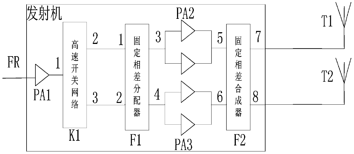
[0023] like figure 1 , 2, a time-sharing dual-output transmitting system of the present invention includes: a driving stage amplifier unit PA1, a high-speed switching network k1, a fixed phase difference distributor F1, final stage amplifier units PA2, PA3, a fixed phase difference combiner F2, and an antenna T1 , T2.

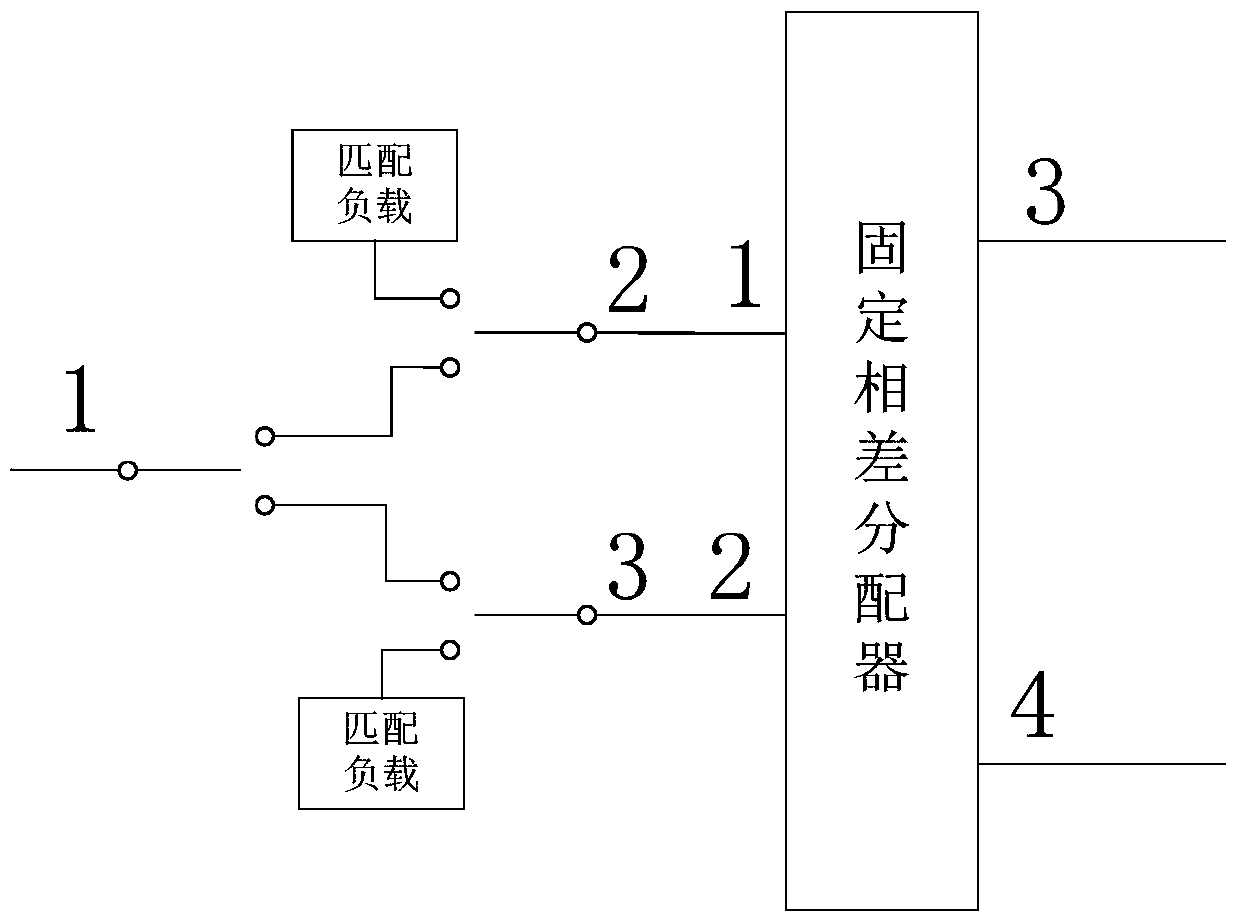
[0024] The output terminal of the driver stage amplifier unit PA1 is connected to the input port 1 of the high-speed switch network K1, the output port 2 of the high-speed switch network K1 is connected to the input port 1 of the fixed phase difference distributor F1, and the output port 3 of the high-speed switch network K1 is distributed with the fixed phase difference connected to the 2 input port of F1.

[0025] The fixed phase difference divider F1 distributes the power of the incoming signal, its output port 3 is connected to the final stage amp...


PUM


Abstract

The invention discloses a time-sharing dual-output transmission system, which includes a sequentially connected driving stage amplifying unit, a power divider, a final stage amplifying unit, a power combiner, a first antenna, a second antenna, a driving stage amplifying unit and power distribution A high-speed switch network is set between the devices. The high-speed switch network includes signal switches with GaAs as the core, and the high-speed switch network is a three-port switch network, including input ports 1, 2, and 3. High-speed switching is performed by controlling the level of the signal. The input port 1 of the switch network is connected with the output port 2 or the output port 3. When the output port 2 of the high-speed switch network is connected with the input port 1, the signal is transmitted to the second antenna. When the output port 3 of the high-speed switch network is connected with the input port When phase 1 is connected, the signal is transmitted to the first antenna. The invention has the advantages that the switching speed is fast, and the switching time of the switch can be effectively controlled, and the insertion loss is smaller compared with the design of a high-power switching switch, and the efficiency of the whole machine is improved.

Description

technical field [0001] The invention relates to the technical field of transmitting in radar, communication and electronic countermeasure systems, in particular to a transmitting system capable of switching at high speed and high efficiency when dual outputs work in time-sharing. Background technique [0002] The transmitter is a device that amplifies the weak radio frequency small signal with a certain working frequency and bandwidth. The transmitter device mainly includes a driver stage amplifier unit, a power divider, a final stage amplifier unit, a power combiner, a circulator (or isolator) and other devices. The principle is that the incoming weak RF small signal is amplified by the driver stage amplifier unit. A certain power is divided into N equal parts by the power divider, and sent to N final stage amplifiers for power amplification, and then the power output by the N final stage amplifiers is combined by the power combiner, and then passes through the isolator or ...

Claims


Application Information

Patent Timeline
Patent Type & Authority Patents(China)
IPC IPC(8): H04B1/04
Inventor 张瑞赵家敏安士全张永慧
Owner CHINA ELECTRONIC TECH GRP CORP NO 38 RES INST
Why Eureka
Try Eureka