A kind of control drive circuit and electronic system

A driving circuit and circuit technology, applied in the direction of electrical program control, program control in sequence/logic controller, engine components, etc., can solve the problems of large current, reduced service life of electronic valves, high power, etc.

Active Publication Date: 2021-08-31
TECH & ENG CENT FOR SPACE UTILIZATION CHINESE ACAD OF SCI
View PDF7 Cites 0 Cited by
  • Summary
  • Abstract
  • Description
  • Claims
  • Application Information

AI Technical Summary

Problems solved by technology

[0002] The electronic valve is a common component used to control the opening or closing of the electronic valve. At present, conventional control circuits such as relays are usually used to design non-magnetic holding solenoid valve control circuits, but the electronic valves designed in this way need to control the voltage High, high current and high power, at the same time, the electronic valve will also generate heat, which greatly reduces the service life of the electronic valve, and it is difficult to meet the actual application needs of the electronic valve for a long time to open and maintain a long life

Method used


Image

  • A kind of control drive circuit and electronic system
  • A kind of control drive circuit and electronic system

Examples


Embodiment Construction

[0046] The following will clearly and completely describe the technical solutions in the embodiments of the present invention with reference to the drawings in the embodiments of the present invention. Obviously, the described embodiments are part of the embodiments of the present invention, not all of them. Based on the embodiments of the present invention, all other embodiments obtained by persons of ordinary skill in the art without making creative efforts shall fall within the protection scope of the present invention.

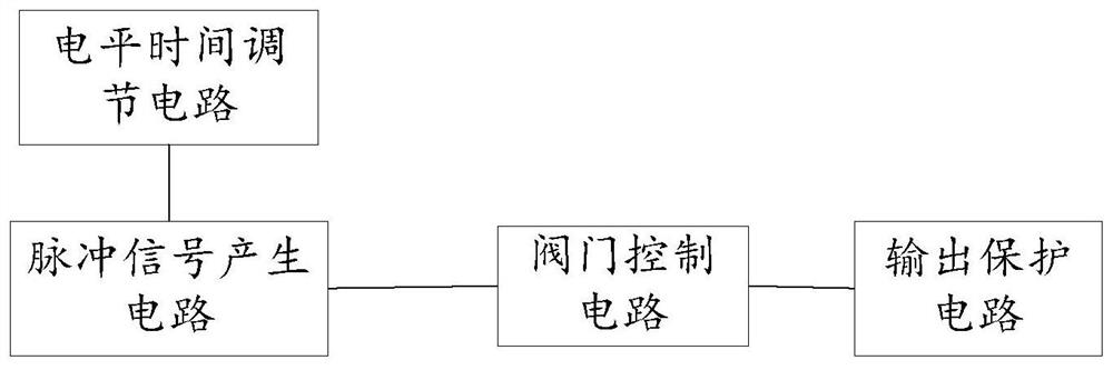
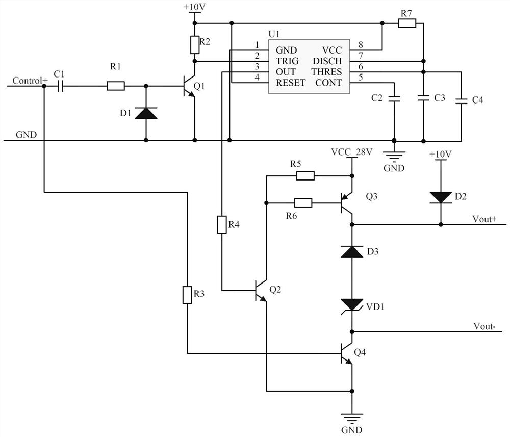
[0047] Such as figure 1 As shown in the structural diagram of a control drive circuit provided by an embodiment of the present invention, a control drive circuit includes a level time adjustment circuit, a pulse signal generation circuit, a valve control circuit and an output protection circuit.

[0048] The level time adjustment circuit is connected to the pulse signal generating circuit, and is used to adjust the period of the pulse signal output by the ...


PUM


Abstract

The invention relates to a control drive circuit, comprising a level time adjustment circuit, a pulse signal generation circuit, a valve control circuit and an output protection circuit; the level time adjustment circuit is connected to the pulse signal generation circuit, and is used to adjust the pulse signal generation The cycle of the pulse signal output by the circuit; the pulse signal generating circuit is connected to the valve control circuit for outputting the pulse signal to the valve control circuit; the valve control circuit is connected to the output protection circuit for The pulse signal controls the opening of the valve; the output protection circuit is used to suppress the peak voltage generated when the valve is closed. The control drive circuit in the present invention has a simple structure and can be applied to a non-magnetic holding valve control circuit. It is suitable for the application of non-magnetic holding self-locking valve control with different opening times, and can meet the requirements of low power consumption when the valve is opened for a long time. Long life requirements. The invention also relates to an electronic system.

Description

technical field [0001] The invention relates to the technical field of electronic components, in particular to a control drive circuit and an electronic system. Background technique [0002] The electronic valve is a common component used to control the opening or closing of the electronic valve. At present, conventional control circuits such as relays are usually used to design non-magnetic holding solenoid valve control circuits, but the electronic valves designed in this way need to control the voltage High, high current and high power, at the same time, the electronic valve will also generate heat, which greatly reduces the service life of the electronic valve, and it is difficult to meet the actual application needs of the electronic valve for a long time to open and maintain a long life. Contents of the invention [0003] The technical problem to be solved by the present invention is to provide a control drive circuit and an electronic system aiming at the deficienci...

Claims


Application Information

Patent Timeline
Patent Type & Authority Patents(China)
IPC IPC(8): G05B19/04F16K31/02
CPCF16K31/02G05B19/04
Inventor 刘翠红卫晓娜管洪飞李新峰吕宏宇郭林
Owner TECH & ENG CENT FOR SPACE UTILIZATION CHINESE ACAD OF SCI
Why Eureka
Try Eureka