Head device of a trapped vortex combustor and its working method

A combustion chamber and head technology, which is applied in the field of trapped vortex combustion chamber head devices, can solve the problems of complex air intake structure of the front wall of the cavity, unfavorable cooling of the front wall of the cavity, and unfavorable interaction between the cavity and the mainstream of the head. , to achieve the effect of achieving ignition performance and lean oil flameout performance, and reducing fuel consumption.

Active Publication Date: 2019-06-04
NANJING UNIV OF AERONAUTICS & ASTRONAUTICS +1
View PDF6 Cites 0 Cited by
  • Summary
  • Abstract
  • Description
  • Claims
  • Application Information

AI Technical Summary

Problems solved by technology

It still has many deficiencies, mainly in: the structure of the head is too complex and the weight is too heavy; the design of the head is not conducive to controlling the interaction between the cavity and the mainstream; the air intake structure of the front wall of the cavity is complicated, which is not conducive to cooling

Method used


Image

  • Head device of a trapped vortex combustor and its working method
  • Head device of a trapped vortex combustor and its working method
  • Head device of a trapped vortex combustor and its working method

Examples


Embodiment Construction

[0030] The technical solutions of the present invention will be described in detail below in conjunction with the accompanying drawings.

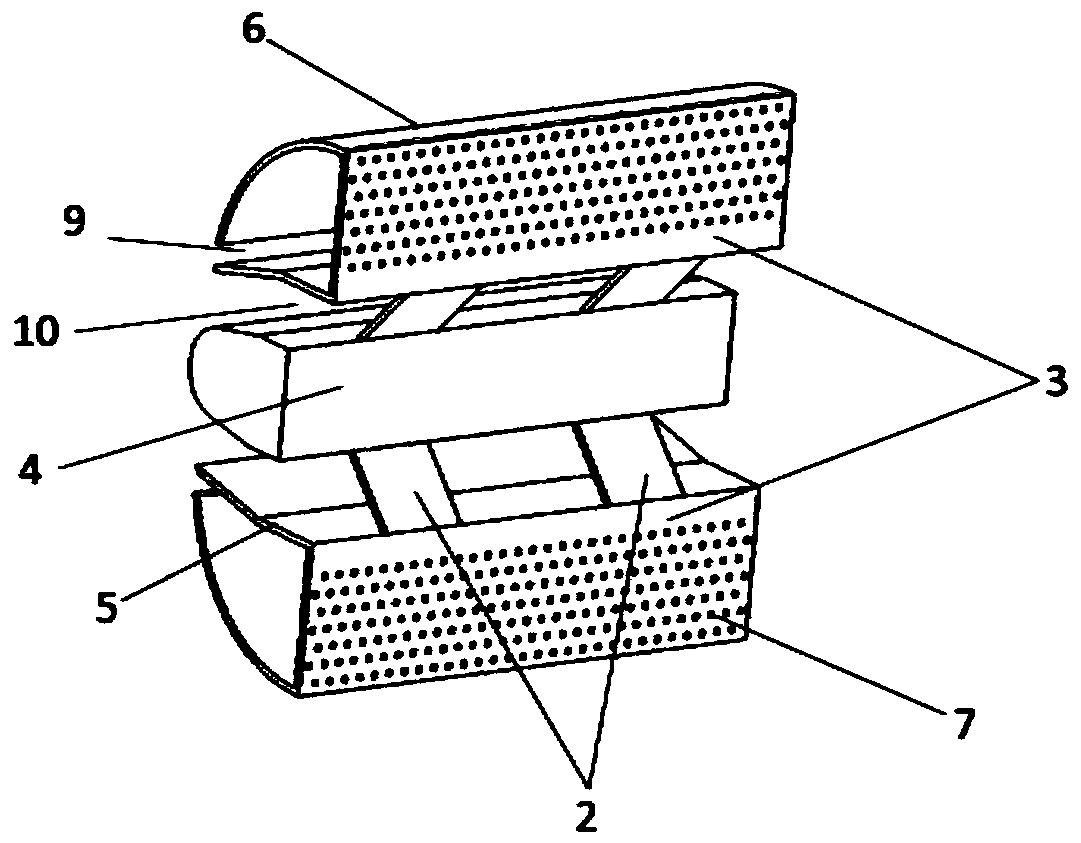
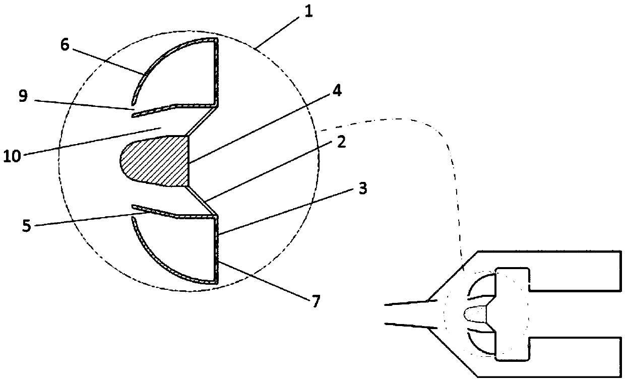
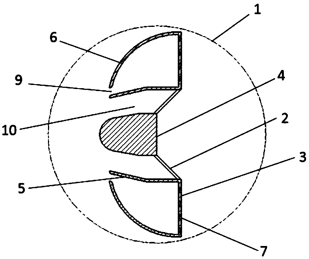
[0031] Please refer to Figure 1 to Figure 4 As shown, a head device 1 of a trapped vortex combustion chamber of the present invention includes a central blunt body 4 , an inclined cross-fire plate 2 , a deflector 5 , a cavity front wall 3 , and a cap 6 . The central blunt body (4) is placed horizontally, with the arc facing forward and the horizontal plane facing backward, and the horizontal plane passing through the central axis is the symmetrical plane; the upper and lower ends of the horizontal plane behind the central blunt body 4 are respectively connected and inclined backward One end of the inclined cross-fire plate 2, the other end of the inclined cross-fire plate 2 is connected to the rear end of the deflector 5, and the deflector 5 is placed horizontally on the upper and lower sides of the central blunt body 4, and the outer wall...


PUM


Abstract

The invention provides a novel trapped vortex combustor head device. The novel trapped vortex combustor head device comprises a central bluff body, a slanted cross-flame plate, a flow deflector, a cavity front wall and a cover hood, wherein the slanted cross-flame plate is connected to the central bluff body; the flow deflector and the cavity front wall are connected to the slanted cross-flame plate; and the cover hood is connected to the cavity front wall. The novel trapped vortex combustor head device has the beneficial effects that main flow of air is led into a low pressure area arranged behind the central bluff body through the central bluff body arranged at the front and the slanted cross-flame plate connected to the central bluff body to prevent plenty of main flow of air from being entrained into a cavity, therefore, the influence of the main flow of air on cavity flowing is reduced, the interaction of the main flow and the cavity is controlled, and the improvement of the ignition performance and lean blowout performance of a trapped vortex combustor is realized.

Description

technical field [0001] The invention belongs to the technical field of combustion control, and in particular relates to a head device of a vortex combustor, in particular to a head device of a vortex combustor applied to a combustor of a military-civil dual-purpose aircraft engine, and a combustion chamber of a ground and ship gas turbine . Background technique [0002] The concept of trapped vortex combustor (Trapped Vortex Combustor, TVC) was first proposed by Professor Hsu of the University of Dayton in the United States, and completed the design and experimental research of the first generation experimental model of trapped vortex combustor with the support of the US Air Force. The first-generation vortex combustor is composed of a cavity precursor (Forebody), a cavity rear body (Afterbody) and a cavity center body (Centerbody) in series. The jets co-spray into the cavity. Compared with the traditional swirl combustor, the recirculation zone formed by the vortex combus...

Claims


Application Information

Patent Timeline
Patent Type & Authority Patents(China)
IPC IPC(8): F23R3/18
CPCF23R3/18
Inventor 金义何小民李明玉赵玉玲
Owner NANJING UNIV OF AERONAUTICS & ASTRONAUTICS
Why Eureka
Try Eureka