Air conditioner in machine room
A computer room air conditioner and cabinet technology, applied in the field of air conditioning, can solve the problems of unreasonable air intake grille design, poor cooling and energy saving effect of computer room air conditioners, improve cooling and energy saving effects, reduce overall cost and energy waste, Reduce the effect of insufficient heat exchange
- Summary
- Abstract
- Description
- Claims
- Application Information
AI Technical Summary
Problems solved by technology
Method used
Image
Examples
Embodiment 1
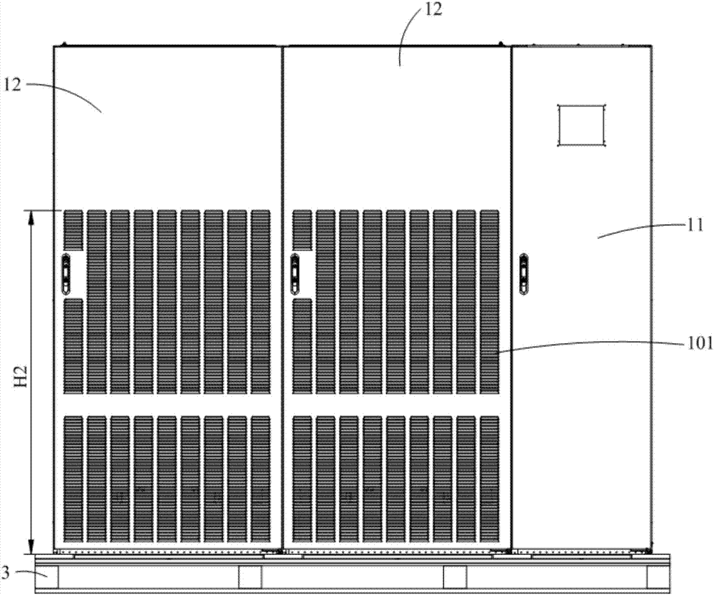
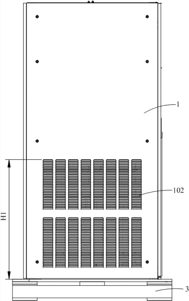
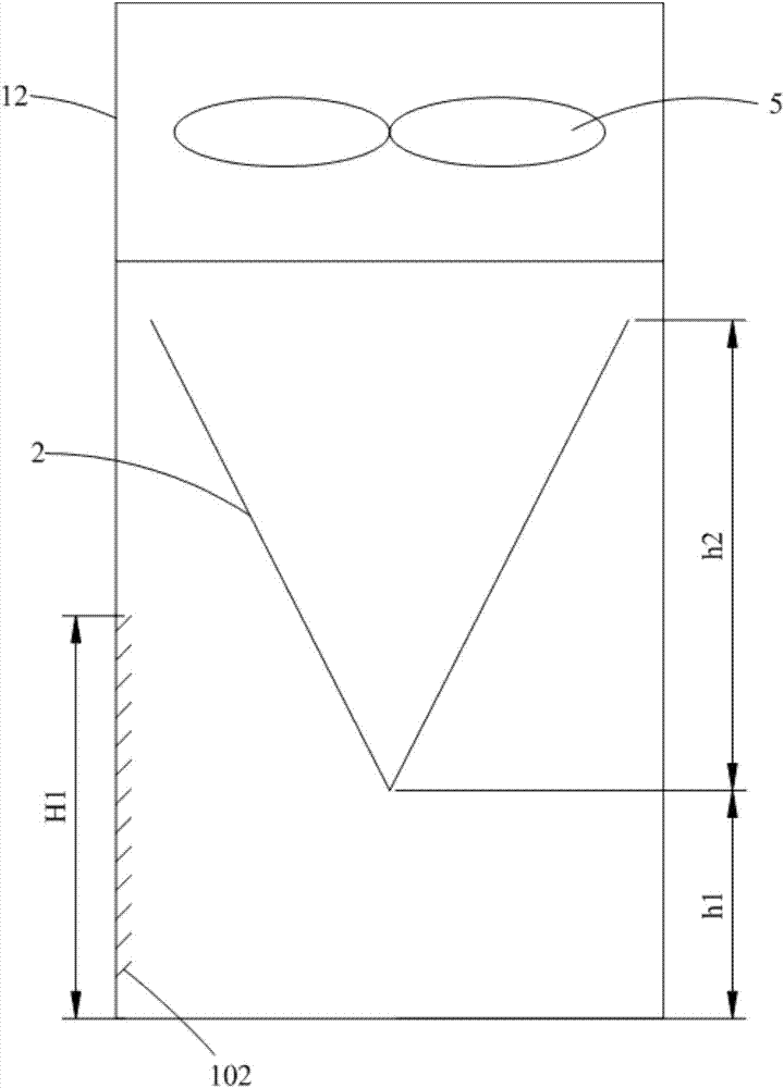
[0045] Such as Figure 1-7 As shown, the computer room air conditioner provided by Embodiment 1 of the present invention includes a cabinet assembly 1 and a heat exchanger 2 disposed in the cabinet assembly 1. The cabinet assembly 1 has positive air inlets located on different sides of the heat exchanger 2. The grille 101 and the lateral air intake grille 102, the vertical distance between the top of the lateral air intake grille 102 and the bottom of the cabinet assembly 1 H1=h1+a*h2, where h1 is the heat exchanger 2 The vertical distance between the bottom of and the bottom of the cabinet assembly 1, h2 is the height of the heat exchanger 2, 0<a<1.
[0046]Specifically, a can be defined as the lateral heat transfer coefficient of the computer room air conditioner, which can be used as a correction coefficient. The forward air intake grille 101 is located on the front of the cabinet assembly 1, and the front of the cabinet assembly 1, that is, the cabinet assembly 1 is place...
Embodiment 2
[0070] The main difference between the computer room air conditioner provided by this embodiment and the first embodiment is that the cabinet assembly 1 is set in a different way, which is specifically reflected in: refer to Figure 1-7As shown, in Embodiment 1, the cabinet assembly 1 includes a control cabinet 11 and at least one heat exchange cabinet 12, the control cabinet 11 and each heat exchange cabinet 12 are arranged side by side, and the control cabinet 11 is provided with an electric control box 4. Each heat exchange cabinet 12 is equipped with a heat exchanger 2, and the front of each heat exchange cabinet 12 is provided with a forward air intake grille 101, and each heat exchange cabinet 12 is connected to the control cabinet The non-contact sides of the body 11 are all provided with side air intake grilles 102; Figure 8-10 As shown, in this embodiment, the cabinet assembly 1 includes a heat exchange cabinet 12, the heat exchange cabinet 12 is provided with an ele...
Embodiment 3
[0076] The main difference between the computer room air conditioner provided in this embodiment and Embodiment 1 and Embodiment 2 is that the arrangement of the cabinet assembly 1 is different, which is specifically reflected in: refer to Figure 11-13 As shown, in this embodiment, the cabinet assembly 1 includes at least two heat exchange cabinets 12 arranged side by side, each heat exchange cabinet 12 is provided with a heat exchanger 2, and each heat exchange cabinet 12 has a A forward air intake grill 101 and a lateral air intake grill 102 are provided, and at least one heat exchange cabinet 12 is also provided with an electric control box 4 . Specifically, in this embodiment, at least two heat exchangers 2 are provided, and one electric control box 4 is provided, and one heat exchanger 2 and the electric control box 4 are installed in the same cabinet. Compared with Embodiment 1, the computer room air conditioner provided by this embodiment is more compact in structure, ...
PUM
 Abstract
Description
Claims
Application Information
 - R&D
- Intellectual Property
- Life Sciences
- Materials
- Tech Scout
- Unparalleled Data Quality
- Higher Quality Content
- 60% Fewer Hallucinations
Browse by: Latest US Patents, China's latest patents, Technical Efficacy Thesaurus, Application Domain, Technology Topic, Popular Technical Reports.
© 2025 PatSnap. All rights reserved.Legal|Privacy policy|Modern Slavery Act Transparency Statement|Sitemap|About US| Contact US: help@patsnap.com


