
Air conditioner system and evaporation temperature control method thereof

A technology for evaporating temperature and air conditioning system, which is applied to compressors with multiple evaporators, refrigerators, refrigeration components, etc. The effect of improving user experience

Inactive Publication Date: 2017-06-30
GD MIDEA HEATING & VENTILATING EQUIP CO LTD +1
View PDF5 Cites 47 Cited by
  • Summary
  • Abstract
  • Description
  • Claims
  • Application Information

AI Technical Summary

Problems solved by technology

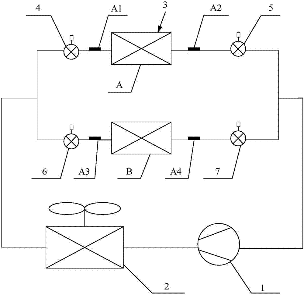
For the air-conditioning system with multiple indoor units connected in parallel, the traditional control method is to control the opening of the electronic expansion valve at the inlet of each indoor unit. However, since the outlets of each indoor unit are directly connected, the pressure at the outlet is the same. , if the pressure loss inside the evaporator of the indoor unit is ignored, the evaporation pressure of different indoor units is almost the same, and the evaporation temperature of each indoor unit cannot be controlled separately; in addition, in the traditional control method, the electronic expansion valve at the inlet of the indoor unit is changed The opening degree can only change the refrigerant flow through the corresponding indoor unit, but also cannot control the evaporation temperature of each indoor unit

Method used


Image

  • Air conditioner system and evaporation temperature control method thereof
  • Air conditioner system and evaporation temperature control method thereof
  • Air conditioner system and evaporation temperature control method thereof

Examples


Embodiment Construction

[0046] The following will clearly and completely describe the technical solutions in the embodiments of the present invention with reference to the accompanying drawings in the embodiments of the present invention. Obviously, the described embodiments are only part of the embodiments of the present invention, not all of them. Based on the embodiments of the present invention, all other embodiments obtained by persons of ordinary skill in the art without creative efforts fall within the protection scope of the present invention.

[0047] It should be noted that if directional indications (such as up, down, left, right, front, back, etc.) are involved in the embodiments of the present invention, they are only used to explain each If the relative positional relationship, movement conditions, etc. between the components change, the directional indication will also change accordingly.

[0048]In addition, if the description of "first", "second" and so on in the present invention is...


PUM


Abstract

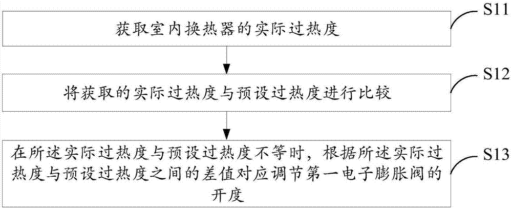
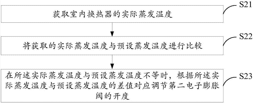
The invention discloses an air conditioner system which comprises a compressor, an outdoor heat exchanger and indoor heat exchangers connected in parallel. The compressor, the outdoor heat exchanger and the indoor heat exchangers are sequentially connected to form a refrigerant circulation loop. The side, close to the outdoor heat exchanger, of each indoor heat exchanger is provided with a first electronic expansion valve. The side, close to the compressor, of each indoor heat exchanger is provided with a second electronic expansion valve. The air conditioner system further comprises a controller. When the controller obtains the information that the practical superheat degree of the indoor heat exchangers is not equal to the preset superheat degree, the opening of the first electronic expansion valves is correspondingly adjusted according to the difference value between the practical superheat degree and the preset superheat degree; and or when the controller obtains the information that the practical evaporation temperature of the indoor heat exchangers it not equal to the preset evaporation temperature, the opening of the second electronic expansion valve is correspondingly adjusted according to the difference value between the practical evaporation temperature and the preset evaporation temperature. The invention further discloses an evaporation temperature control method of the air conditioner system. The evaporation temperature of multiple indoor units which are connected in parallel in the air conditioner system can be independently controlled.

Description

technical field [0001] The invention relates to the technical field of refrigeration, in particular to an air conditioning system and an evaporation temperature control method thereof. Background technique [0002] With the improvement of living standards, users have higher and higher requirements for the temperature and humidity of the air supplied by the air-conditioning system, which requires the control of the amount of refrigerant and the evaporation temperature of the indoor unit. For the air-conditioning system with multiple indoor units connected in parallel, the traditional control method is to control the opening of the electronic expansion valve at the inlet of each indoor unit. However, since the outlets of each indoor unit are directly connected, the pressure at the outlet is the same. , if the pressure loss inside the evaporator of the indoor unit is ignored, the evaporation pressure of different indoor units is almost the same, and the evaporation temperature ...

Claims


Application Information

Patent Timeline
IPC IPC(8): F25B5/02F25B41/06F25B49/02F25B41/31
CPCF25B5/02F25B49/02F25B2700/21174F25B2700/21175F25B2600/2513F25B2313/0233F25B41/31Y02B30/70
Inventor 王威许永锋梁伯启薛晓
Owner GD MIDEA HEATING & VENTILATING EQUIP CO LTD
Learn More