Gas flow rate and pressure relationship demonstration instrument

A technology of gas flow rate and demonstration instrument, which is applied in instruments, educational appliances, teaching models, etc., can solve the problems of poor persuasiveness of experimental phenomena, poor understanding of the relationship between gas pressure and flow rate, and inability to measure gas pressure values.

Inactive Publication Date: 2017-06-30
CHINA WEST NORMAL UNIVERSITY
View PDF13 Cites 2 Cited by
  • Summary
  • Abstract
  • Description
  • Claims
  • Application Information

AI Technical Summary

Problems solved by technology

[0004] The disadvantage of the appealing experimental device is that the thickness of the glass tube is fixed everywhere. When blowing a gas with a certain flow rate, the ratio of the flow rate in the thick tube to the thin tube cannot be changed. The flow velocity in the tube can only increase with the increase of the flow velocity of the external airflow, and decrease with the decrease of the flow velocity of the external airflow. Even if there are many experiments, only the experimental phenomenon with basically the same scale is obtained each time. The specific performance is The height difference of the liquid surface on both sides of the U-shaped tube is basically the same, which leads to poor convincin

Method used


Image

  • Gas flow rate and pressure relationship demonstration instrument
  • Gas flow rate and pressure relationship demonstration instrument
  • Gas flow rate and pressure relationship demonstration instrument

Examples


Embodiment Construction

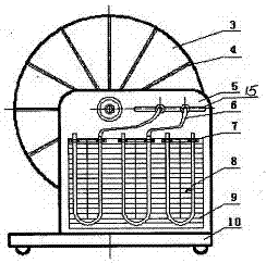
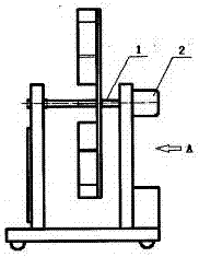
[0014] Such as figure 1 and figure 2 As shown, the demonstration instrument shown is supported by a base 10 with two vertical plates, including a left support plate 5 and a right support plate 11. There are holes on the two plates to support an impeller support shaft 1, and one end of the shaft is connected with a speed-regulating DC motor 2 , control the rotation of the impeller disk 3, a group of impeller blades 4 are distributed on the impeller disk, wind force is generated when the impeller disk 3 rotates, a group of micro pressure gauges 8 are installed on the front of the left support plate 5, and the u-shaped pipe of the micro pressure gauge is fixed with a fixing clip 7 On the board, there is a scale 9 engraved on the board. Observe the liquid level of the color liquid in the U-shaped tube to measure the pressure value. One end of the U-shaped tube is connected with a latex tube 6, and a measuring head of a micro pressure gauge is connected to it. Or the probe of pre...


PUM


Abstract

The invention discloses a gas flow rate and pressure relationship demonstration instrument. A base (10) is arranged. Two vertical plates which are arranged with spacing are arranged in parallel on the base. A fan impeller is arranged between two vertical plates. Both ends of the impeller shaft (1) are supported in through holes arranged in two vertical plates. One end is connected with a speed controlled motor (2) arranged on a vertical plate. A set of micro pressure gauges (8) is arranged on the front side of the other vertical plate. The U-shaped tubes of the micro pressure gauges are fixed on the plate face. Scales are engraved on the plate face. The probes or pressure sensors of the micro pressure gauges are arranged in a chute (15) arranged on a plate face. The chute is a through hole which is communicated with the back. The position of each probe is adjustable, so that the wind speed of different locations can be felt. According to the invention, students can visually feel the relationship between flow rate and pressure in a fluid, and can better understand the Bernoulli's law.

Description

technical field [0001] The invention generally relates to a physical experiment device, in particular to an experimental device for quantitatively exploring and demonstrating the relationship between gas flow velocity and pressure and the Bernoulli equation. Background technique [0002] In a fluid system, such as air flow and water flow, the faster the flow velocity, the smaller the pressure generated by the fluid. This is Daniel Bernoulli's law, known as the father of fluid mechanics. The content of Bernoulli's law is: from Bernoulli's law when the incompressible, ideal fluid flows steadily along the flow tube, the flow velocity increases, the static pressure of the fluid will decrease; conversely, the flow velocity decreases, the fluid static pressure will increase. Its essence is the conservation of mechanical energy of the fluid, namely: kinetic energy + gravitational potential energy + pressure potential energy = constant. Bernoulli's law is widely used in hydraulics...

Claims


Application Information

Patent Timeline
IPC IPC(8): G09B23/12
CPCG09B23/12
Inventor 代伟罗洁曹彪
Owner CHINA WEST NORMAL UNIVERSITY
Why Eureka
Try Eureka