Energy quick transfer-based hybrid direct current super-conductive current limiter

A superconducting current limiter, a hybrid technology, applied in the usage of superconducting elements, emergency protection circuit devices for limiting overcurrent/overvoltage, electrical components, etc., can solve the problem of lack of resistive components and current limiting resistance Reaching the maximum value, long self-recovery time and other problems, to achieve the effect of improving transient stability and steady-state security, maintaining relay protection configuration and stability, and simple equipment structure

Active Publication Date: 2017-07-04
HUAZHONG UNIV OF SCI & TECH
View PDF7 Cites 3 Cited by
  • Summary
  • Abstract
  • Description
  • Claims
  • Application Information

AI Technical Summary

Problems solved by technology

[0008] In the DC system, the resistive current limiter uses the quench characteristics of superconducting materials to realize automatic triggering, automatic current limiting, and rapid response when a fault occurs. Weak, it is difficult to control the quench process, which reduces the reliability of the equipment, and the self-recovery time is long; in the DC system, the inductive current limiter automatically limits the current when it fails, responds quickly, and can well limit the peak value of the short-circuit current. The disadvantage is the lack of resistive components, the short-circuit current tends to be stable before the fault is removed, and the inductance of the current limiter cannot suppress the steady-state short-circuit current

Method used


Image

  • Energy quick transfer-based hybrid direct current super-conductive current limiter
  • Energy quick transfer-based hybrid direct current super-conductive current limiter
  • Energy quick transfer-based hybrid direct current super-conductive current limiter

Examples


Embodiment Construction

[0038] In order to make the object, technical solution and advantages of the present invention clearer, the present invention will be further described in detail below in conjunction with the accompanying drawings and embodiments. It should be understood that the specific embodiments described here are only used to explain the present invention, not to limit the present invention. In addition, the technical features involved in the various embodiments of the present invention described below can be combined with each other as long as they do not constitute a conflict with each other.

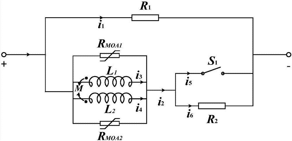
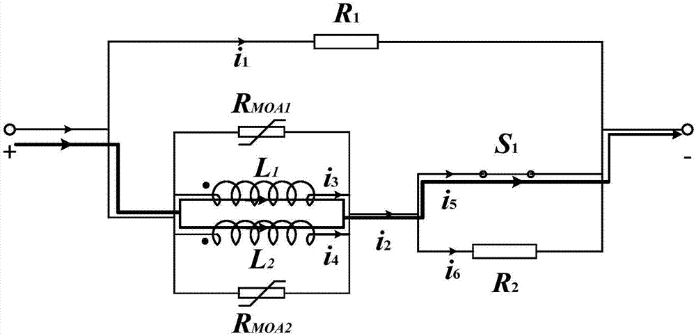
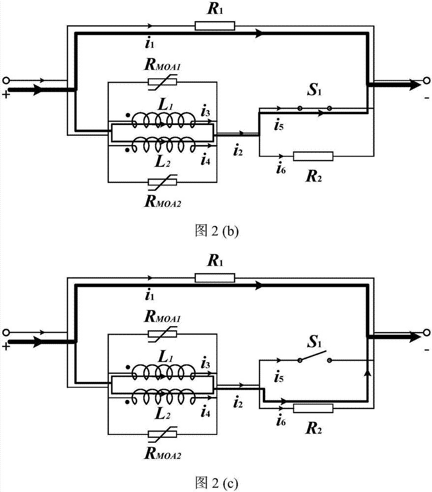
[0039] The invention provides a hybrid DC superconducting current limiter based on rapid energy transfer, which includes an inductance coil, a DC fast switch, a bypass resistor, a fixed value resistor and a metal oxide arrester, wherein the two inductance coils are composed of Wound with superconducting wires, the two inductance coils have the same number of turns, the same structure, forward co...


PUM


Abstract

The invention discloses an energy quick transfer-based hybrid direct current super-conductive current limiter, and belongs to the technical field of electrical engineering. The energy quick transfer-based hybrid direct current super-conductive current limiter comprises two inductive coils, a direct current quick switch, a bypass resistor, a fixed value resistor, and metal oxide lightning arresters, wherein the two inductive coils are connected in parallel; the two inductive coils are wound by super-conductive wires with the same number of turns and consistent structures, and the magnetic fluxes of the coils are coupled forwardly; the direct current quick switch is connected with the super-conductive inductive coils in series as a whole to form a series branch; the bypass resistor is connected with the two ends of the series branch in parallel; the fixed value resistor is connected with the two ends of the quick switch in parallel; and the two metal oxide lightning arresters are connected at the two ends of the two inductive coils in parallel respectively. The current limiter disclosed by the invention can provide a super-conductive-state and resistance-loss-free smoothening electric reactance for a power transmission line at a normal state of a direct current system, can rapidly and effectively suppress peak of a short circuit current when the direct current system suffers from a monopole grounding fault or a two-stage short-circuit fault, and also can protect safe and stable operation of the super-conductive inductive coils.

Description

technical field [0001] The invention belongs to the technical field of electric engineering, and more precisely, the invention relates to a fault current limiter suitable for short-circuit protection of power systems. Background technique [0002] To build the Energy Internet, one of the important methods that can be selected for future transmission network construction is voltage source high-voltage direct current transmission (VSCHVDC). The problem of rapid disconnection of DC short-circuit fault current is one of the key technical issues to be solved urgently for VSC-HVDC power grids. [0003] At present, although high-voltage DC circuit breakers are considered to be one of the effective ways to solve the problem of short-circuit faults in DC power grids, with the continuous development of power grids and the continuous increase of transmission capacity, the level of short-circuit current continues to increase. When the short-circuit current exceeds When the interrupting ...

Claims


Application Information

Patent Timeline
IPC IPC(8): H02H9/02
CPCH02H9/02H02H9/023Y02E40/60
Inventor 任丽梁思源唐跃进徐颖夏仲王作帅石晶李敬东张立晖严思念杨张伟张意
Owner HUAZHONG UNIV OF SCI & TECH
Why Eureka
Try Eureka