Card code printing mechanism with light elastic piece

A shrapnel and card technology, which is applied in the field of card coding mechanism, can solve the problems of difficulty in controlling the rotation accuracy of the dial, high production cost of the dial, and high quality of the dial mechanism.

Pending Publication Date: 2017-07-07
SHENZHEN SILONE TONGHUI TECH
View PDF12 Cites 3 Cited by
  • Summary
  • Abstract
  • Description
  • Claims
  • Application Information

AI Technical Summary

Problems solved by technology

[0003] The present invention aims to solve the problems that the existing dial mechanism has a large mass, it is difficult to control the rotation accuracy of the dial, and the production cost of the dial is high, and further provides a card coding mechanism with a light spring

Method used


Image

  • Card code printing mechanism with light elastic piece
  • Card code printing mechanism with light elastic piece
  • Card code printing mechanism with light elastic piece

Examples


specific Embodiment approach 1

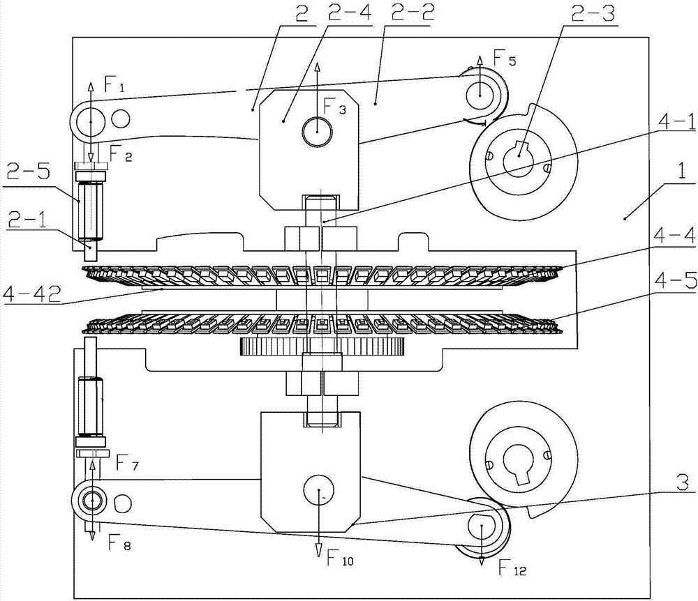
[0019] Specific implementation mode one: combine Figure 1 ~ Figure 3 Describe this embodiment, a card coding mechanism with light-duty shrapnel, which includes a vertical plate bracket 1, a dial assembly, a first hammer assembly 2 and a second hammer assembly 3, the dial assembly, the second hammer assembly Both the hammer assembly 2 and the second hammer assembly 3 are fixed on the vertical plate bracket 1, and the first hammer assembly 2 and the second hammer assembly 3 are symmetrically arranged on the upper and lower sides of the dial assembly both ends,

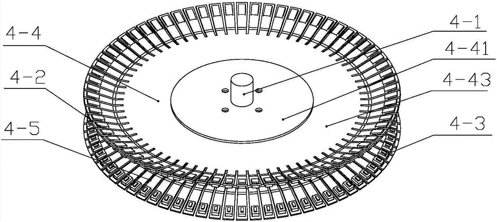
[0020] The dial assembly includes a dial shaft 4-1, several first fonts 4-2, several second fonts 4-3, symmetrically arranged first circular dials 4-4 and second circular dials 4- 5. Both the first round dial 4-4 and the second round dial 4-5 are rotatably fixed on the dial shaft 4-1 through bearings, and the first round dial 4-4 includes the second round dial 4-5. An inner disc 4-41, a first outer disc 4-42 and a fir...

specific Embodiment approach 2

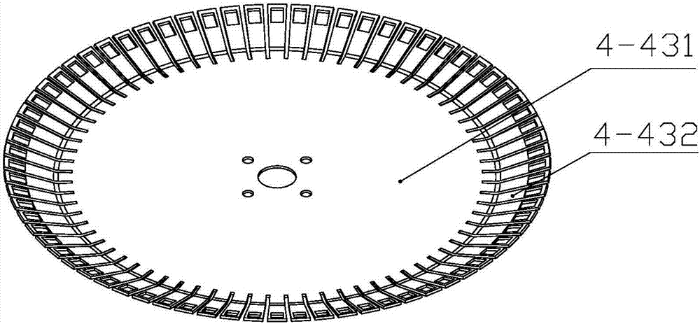
[0022] Specific implementation mode two: combination Figure 1 ~ Figure 3 To illustrate this embodiment, the first elastic strip 4-432 and the second elastic strip are in the shape of bent strips. In such a design, the bending angle of the bending part of the elastic strip is related to the length of the elastic strip and the distance between the first elastic strip and the second elastic strip, so that when the first font 4-2 and the second font 4-3 are pressed together , the two fonts fit together horizontally. Other compositions and connections are the same as those in the first embodiment.

specific Embodiment approach 3

[0023] Specific implementation mode three: combination Figure 1~3 To illustrate this embodiment, the first hammer assembly 2 and the second hammer assembly 3 are symmetrically arranged at both ends of the dial shaft 4-1, and the first hammer assembly 2 includes the first hammer 2- 1. The first character arm 2-2 and the first cam component 2-3, the first cam component 2-3 is fixed on the vertical plate bracket 1, and one end of the first character arm 2-2 is vertically fixed with the first character hammer 2-1, and the first word hammer 2-1 is located between the first word arm 2-2 and the dial assembly, and the other end of the first word arm 2-2 always abuts against the first cam assembly 2-3 On the surface of the cam, the axial center of the first character arm 2-2 is hingedly installed on the top of the dial shaft 4-1 through the first fixed block 2-4, and the dial shaft 4-1 is simultaneously located on the first circular dial 4-4 The center position of and the center pos...


PUM


Abstract

The invention provides a card code printing mechanism with a light elastic piece and belongs to the technical field of identification card printing. The card code printing mechanism solves the problems that an existing case mechanism is large in mass, the case rotating precision is difficult to control, and the production cost of cases is high. A first circular case and a second circular case are both rotationally and fixedly connected to a case shaft through bearings. The first circular case comprises a first inner disc, a first outer disc and the first disc-shaped elastic piece. The first disc-shaped elastic piece comprises a first base plate and multiple first elastic piece strips evenly arranged in the circumferential direction of the first base plate. The first base plate is fixedly connected between the first inner disc and the first outer disc. The end, fixedly connected with the first base plate, of each first elastic piece strip is the fixed end, and the other end of each first elastic piece is the movable end. Multiple first matrixes are arranged at the movable ends of the first elastic piece strips in a one-to-one manner. Multiple second matrixes are arranged at the movable ends of the second elastic strips in the second circular case in a one-to-one manner. The card code printing mechanism is used for printing of identification cards.

Description

technical field [0001] The invention relates to a card coding mechanism, which belongs to the technical field of card printing. Background technique [0002] Card coding equipment is now widely used in bank card production, and the dial in card coding equipment is especially important for the printing quality of concave and convex characters on cards. The dials of existing card coding mechanisms generally use metal casting, CNC (Numerical control machine tool) processing and other process production, the processing cost is high, the processing is difficult, and the position is limited by the dial groove, the font is long, and the dial needs a certain thickness to make the font have enough travel, which increases the weight of the dial. The mass of the dial is large, resulting in a large moment of inertia, and it is difficult to control the rotation accuracy of the dial and the position accuracy of the font, so that it cannot rotate at a high speed, which limits the rotation ...

Claims


Application Information

Patent Timeline
Patent Type & Authority Applications(China)
IPC IPC(8): B41K3/40B41K3/62
CPCB41K3/40B41K3/62
Inventor 巨琳辉
Owner SHENZHEN SILONE TONGHUI TECH
Why Eureka
Try Eureka