
Pan head cross self-drilling screw and processing process thereof

A technology of drilling tail screws and pan heads, which is applied in the direction of screws, nuts, bolts, etc., which can solve the problems of reducing connection strength and connection life, high temperature resistance of drilling tail screws, time-consuming and labor-intensive problems, etc., to improve anti-embroidery performance and drill holes Efficient, easy-to-use effects

Inactive Publication Date: 2017-07-07
江苏固德建筑机械有限公司
View PDF5 Cites 18 Cited by
  • Summary
  • Abstract
  • Description
  • Claims
  • Application Information

AI Technical Summary

Problems solved by technology

[0004] There are still certain problems in the existing drill tail screws. When the drill tail screws are drilled in, the drill tail screws are easy to slip when locked, and it takes time and effort; the existing drill tail screws have poor sealing performance, and external water, dust, etc. It is easy for objects to enter the screw connection part, which reduces the connection strength and connection life
Existing drill tail screws are not resistant to high temperature, easy to oxidize, easy to corrode, and not resistant to embroidery

Method used


Image

  • Pan head cross self-drilling screw and processing process thereof
  • Pan head cross self-drilling screw and processing process thereof

Examples


Embodiment 1

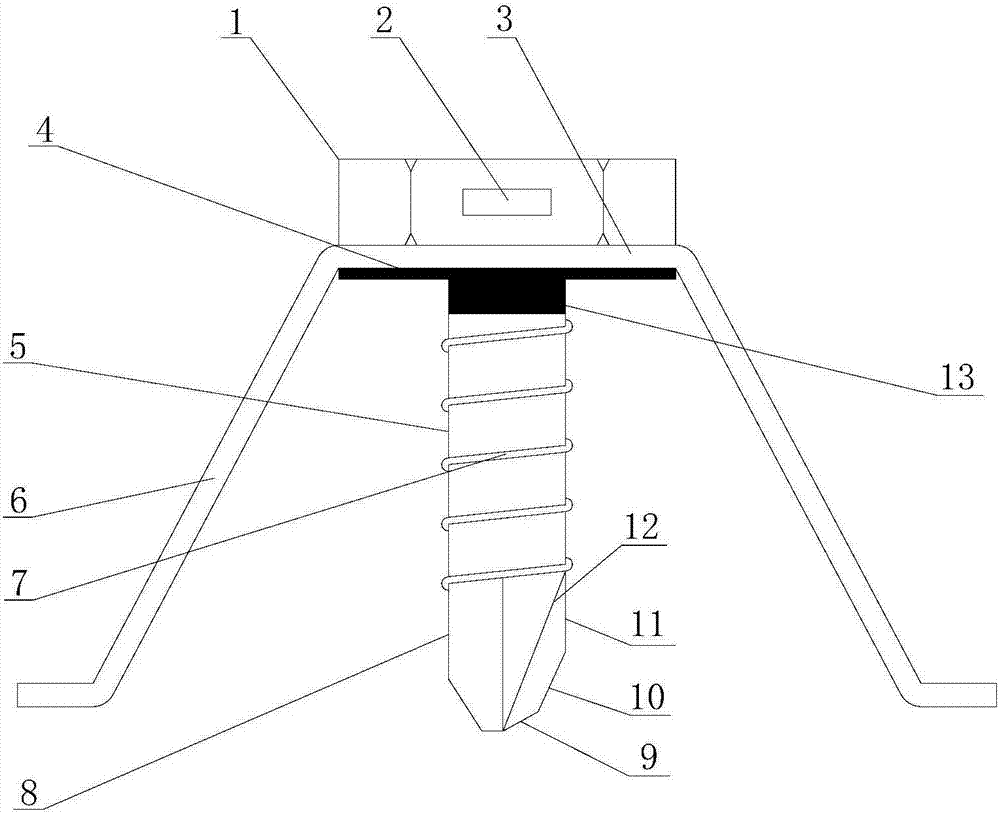
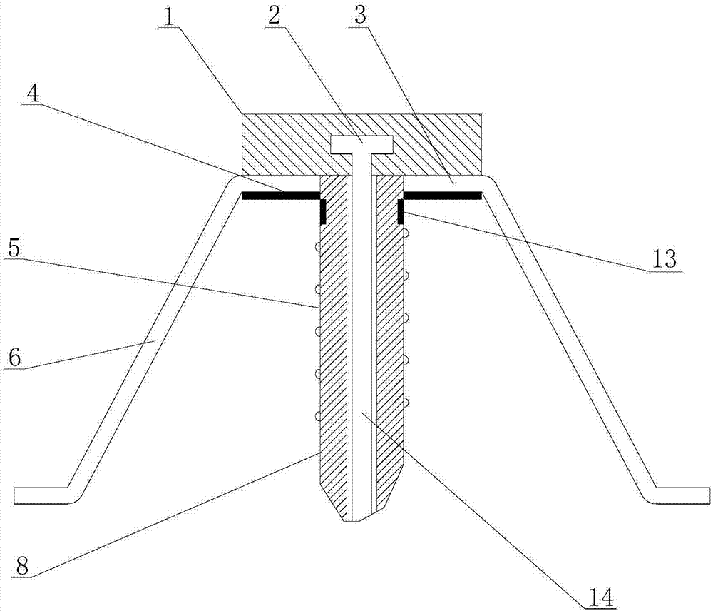
[0051] A kind of pan head cross-drilling screw of this embodiment, such as figure 1 with 2 As shown, it includes pan head 1, support gasket 3, screw rod 5 and drill tail 8. Pan head 1 is in the shape of a hexagonal column. A chip discharge port 2 is provided on the side of pan head 1, and a support pad is provided at the lower end of pan head 1. Sheet 3, the lower surface of the support gasket 3 is covered with the first water-expandable waterstop 4, the upper end of the screw rod 5 runs through the support gasket 3 and is fixedly connected to the lower end of the pan head 1, and the screw rod 5 is provided with an external thread 7, and the screw rod 5 The lower end is fixedly connected with the drill tail 8, and the middle part of the screw rod 5 is provided with a through hole 14 from top to bottom, the upper end of the through hole 14 communicates with the chip discharge port 2, and the lower end of the through hole 14 extends to the lowermost end of the screw tail 8, and ...

Embodiment 2

[0077] A kind of pan head cross-drilling screw of this embodiment, such as figure 1 with 2 As shown, it includes pan head 1, support gasket 3, screw rod 5 and drill tail 8. Pan head 1 is in the shape of a hexagonal column. A chip discharge port 2 is provided on the side of pan head 1, and a support pad is provided at the lower end of pan head 1. Sheet 3, the lower surface of the support gasket 3 is covered with the first water-expandable waterstop 4, the upper end of the screw rod 5 runs through the support gasket 3 and is fixedly connected to the lower end of the pan head 1, and the screw rod 5 is provided with an external thread 7, and the screw rod 5 The lower end is fixedly connected with the drill tail 8, and the middle part of the screw rod 5 is provided with a through hole 14 from top to bottom, the upper end of the through hole 14 communicates with the chip discharge port 2, and the lower end of the through hole 14 extends to the lowermost end of the screw tail 8, and ...

Embodiment 3

[0103] A kind of pan head cross-drilling screw of this embodiment, such as figure 1 with 2 As shown, it includes pan head 1, support gasket 3, screw rod 5 and drill tail 8. Pan head 1 is in the shape of a hexagonal column. A chip discharge port 2 is provided on the side of pan head 1, and a support pad is provided at the lower end of pan head 1. Sheet 3, the lower surface of the support gasket 3 is covered with the first water-expandable waterstop 4, the upper end of the screw rod 5 runs through the support gasket 3 and is fixedly connected to the lower end of the pan head 1, and the screw rod 5 is provided with an external thread 7, and the screw rod 5 The lower end is fixedly connected with the drill tail 8, and the middle part of the screw rod 5 is provided with a through hole 14 from top to bottom, the upper end of the through hole 14 communicates with the chip discharge port 2, and the lower end of the through hole 14 extends to the lowermost end of the screw tail 8, and ...


PUM


Abstract

The invention discloses a pan head cross self-drilling screw and a processing process thereof. The pan head cross self-drilling screw comprises a pan head body, a supporting gasket, a screw and a drill tail, wherein the pan head is in the shape of a hexagonal prism; at least one chip removal hole is formed in the side surface of the pan head; the supporting gasket is arranged at the lower end of the pan head; a first water encounter swelling water-stop belt covers the lower surface of the supporting gasket; the upper end of the screw penetrates through the supporting gasket and is fixedly connected with the lower end of the pan head; the lower end of the screw is fixedly connected with the drill tail; a through hole is formed in the middle of the screw from top to bottom; the upper end of the through hole communicates with the chip removal hole; inner threads are arranged in the through hole; and at least three elastic supporting pins are fixedly connected on the edge of the supporting gasket uniformly at intervals. When an operator uses the pan head cross self-drilling screw to drill and fasten, the outer threads on the outer part of the screw achieves the effects of drilling and removing chips while the through hole also achieves the effect of drilling and removing chips, so that drilling is more efficient during use, chip removal is smooth, and operation is labor-saving.

Description

technical field [0001] The invention relates to a pan head cross-drilling screw and a processing technology thereof, belonging to the technical field of fastening or fixing components. Background technique [0002] Fasteners are a general term for a type of mechanical parts used to fasten two or more parts (or components) into a whole. They are widely used in various machinery, equipment, vehicles, ships, railways, Bridges, buildings, structures, tools, instruments, chemicals, instruments and supplies, etc., are characterized by a wide variety of specifications, different performances and uses, and a high degree of standardization, serialization, and generalization. [0003] Screw is one of the most commonly used fastening parts. It uses the physical and mathematical principles of the oblique circular rotation and friction of the object, and is a tool for fastening the mechanical parts of the object step by step. Drilling screw is a new invention of people in recent years. ...

Claims


Application Information

Patent Timeline
IPC IPC(8): F16B25/10F16B25/04F16B41/00C22C38/18C22C38/06C22C38/04C22C38/16C22C38/12C22C38/14C22C38/32C23G1/08C21D9/00B23P15/00B21H3/06
CPCB21H3/06B23P15/00C21D9/0093C22C38/002C22C38/005C22C38/008C22C38/04C22C38/06C22C38/12C22C38/14C22C38/16C22C38/18C22C38/32C23G1/08F16B25/103F16B33/004F16B33/008
Inventor 秦方文
Owner 江苏固德建筑机械有限公司
Learn More