Stable speed reduction mechanism using gear graded transmission

A technology of hierarchical transmission and deceleration mechanism, applied in the direction of gear transmission, belt/chain/gear, mechanical equipment, etc., can solve the problems of inability to decelerate, unstable transmission, swing of driven wheel, etc., to achieve good deceleration, improve Use performance and service life, the effect of gear stability

Active Publication Date: 2017-07-07
宁波智启机电有限公司
View PDF5 Cites 1 Cited by
  • Summary
  • Abstract
  • Description
  • Claims
  • Application Information

AI Technical Summary

Problems solved by technology

[0002] The current deceleration device generally uses a belt and a pulley transmission mechanism for deceleration. In this pulley transmission mechanism, the driving wheel connected to the motor rotor shaft drives the driven wheel to rotate through the belt, which not only causes unstable transmission, but also leads to The driving wheel often swings, and the belt is very likely to break under the condition of excessive force, which poses a very large safety hazard. The existing gears are also used for deceleration, but the gears are simply used for deceleration. It does not play a very good deceleration effect, and when the gear is used for deceleration, the meshing connection between the gears will generate a lot of noise. The existing deceleration mechanism has not made a reasonable treatment for this. We propose a robust reduction mechanism utilizing gear staged transmission

Method used


Image

  • Stable speed reduction mechanism using gear graded transmission
  • Stable speed reduction mechanism using gear graded transmission
  • Stable speed reduction mechanism using gear graded transmission

Examples


Embodiment Construction

[0030] The following will clearly and completely describe the technical solutions in the embodiments of the present invention with reference to the accompanying drawings in the embodiments of the present invention. Obviously, the described embodiments are only some, not all, embodiments of the present invention. Based on the embodiments of the present invention, all other embodiments obtained by persons of ordinary skill in the art without making creative efforts belong to the protection scope of the present invention.

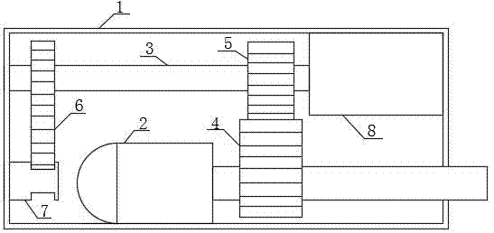
[0031] see Figure 1-10 , the present invention provides a technical solution: a stable deceleration mechanism using gear staged transmission, including a device body 1, a motor 2 is provided at the inner middle end of the device body 1, and one end of the output shaft of the motor 2 runs through the device body 1 And it is located outside one end of the device body 1, the output shaft is fixedly sleeved with the first driving gear 4 on one end close to the mo...


PUM


Abstract

The invention relates to the technical field for speed reduction equipment, in particular to a stable speed reduction mechanism using gear graded transmission. The stable speed reduction mechanism comprises a device body, wherein a motor is arranged at the middle end inside the device body, and one end of an output shaft of the motor penetrates through the device body and is located on the outer side of one end of the device body; a first driving gear is fixedly connected to the end, close to the motor, of the output shaft in a sleeving mode, kinetic power can be gradually graded and transmitted to each speed reduction mechanism, then the condition of dislocation of the gear and the like can be prevented through cooperation work between a speed reduction chamber and an auxiliary speed reduction chamber, so that the speed of the kinetic power can be greatly reduced; meshing connection between the gear is adopted, graded transmission is conducted, so that speed reduction can be effectively conducted, and the gears are more table and efficient in the speed reduction work; and cooperation between a vacuum plate and a muffler can also eliminate the noise caused by meshing connection, working vibration and the noise can be reduced, the service performance is further improved, and service life is further prolonged.

Description

technical field [0001] The invention relates to the technical field of deceleration equipment, in particular to a stable deceleration mechanism utilizing gear staged transmission. Background technique [0002] The current deceleration device generally uses a belt and a pulley transmission mechanism for deceleration. In this pulley transmission mechanism, the driving wheel connected to the motor rotor shaft drives the driven wheel to rotate through the belt, which not only causes unstable transmission, but also leads to The driving wheel often swings, and the belt is very likely to break under the condition of excessive force, which poses a very large safety hazard. The existing gears are also used for deceleration, but the gears are simply used for deceleration. It does not play a very good deceleration effect, and when the gear is used for deceleration, the meshing connection between the gears will generate a lot of noise. The existing deceleration mechanism has not made a ...

Claims


Application Information

Patent Timeline
Patent Type & Authority Applications(China)
IPC IPC(8): F16H1/22F16H57/028F16H57/023
CPCF16H1/22F16H57/023F16H57/028
Inventor 孙立民国际昌
Owner 宁波智启机电有限公司
Why Eureka
Try Eureka